Valveless rotary internal combustion engine

a technology of internal combustion engine and valveless valve, which is applied in the direction of liquid fuel engine, rotary piston liquid engine, machine/engine, etc., can solve the problems of difficult manufacturing of wankel engine, difficult to meet the requirements of wankel engine, and high weight-to-power ratio, so as to save materials, weight, labor and manufacturing costs, and quickly, efficiently and economically convert thermal energy into usable kinetic energy.

Inactive Publication Date: 2011-04-26
KAMENOV KAMEN GEORGE
View PDF22 Cites 15 Cited by
  • Summary
  • Abstract
  • Description
  • Claims
  • Application Information

AI Technical Summary

Benefits of technology

[0014]The primary object of the present invention is to provide a rotary internal combustion engine, which quickly, efficiently and economically converts thermal energy into usable kinetic energy.
[0015]A further object of the present invention is to provide a power plant with essentially one moving element with concomitant savings in materials, weight, labor and manufacturing costs.
[0016]A further object of the present invention is to provide a rotary engine with operating vane wherein the forces on opposite sides of the vanes are essentially balanced and the vibrations are virtually eliminated.

Problems solved by technology

In the past, attempts have been made to improve on reciprocating piston engines but their inherent complexity and high weight-to-power ratio has proven limiting.
Also rotary or Wankel design engines have become relatively highly developed, they still exhibit daunting problems in rotor sealing and cost parameters.
For example, the Wankel engine is difficult to manufacture, it has a short life, it has a problem of loosing its lubrication and seizing up.
It has poor gas mileage, high oil consumption and high exhaust level.
For every three turns of the working piston there is only one rotation of the main power output shaft which results in an excessive friction inside the working chamber between the piston and the casing.
The Tan engine is big and bulky.
It would be difficult to manufacture and repair it.
It would be difficult to balance it and it would only work as a diesel engine.
Barber fails to disclose ports for intake of combustible fluid and lubricating oil, seal strips and external valving means with an appropriate cam shaft.

Method used


Image

  • Valveless rotary internal combustion engine
  • Valveless rotary internal combustion engine
  • Valveless rotary internal combustion engine

Examples


Embodiment Construction

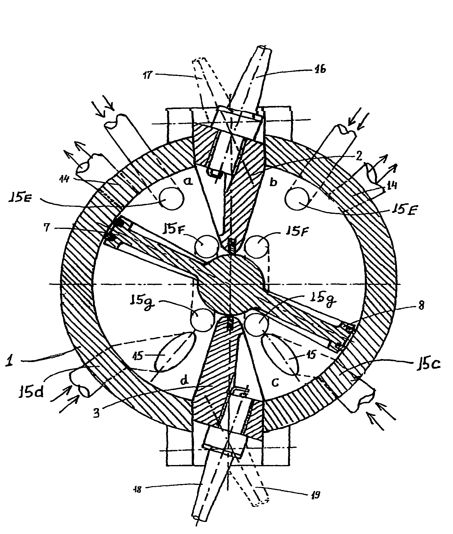
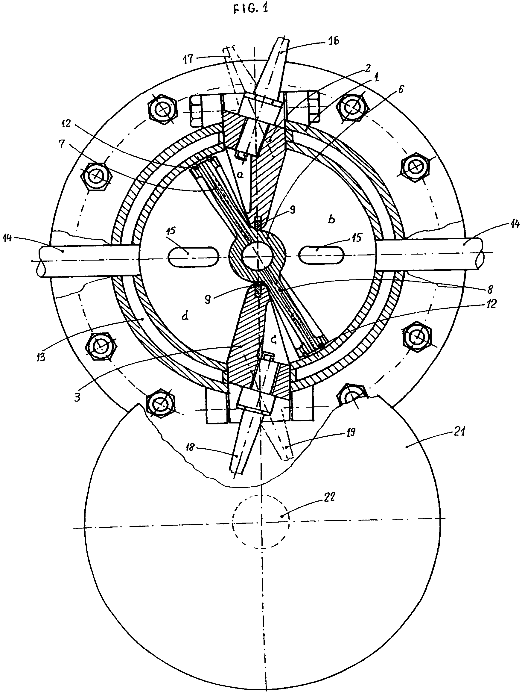
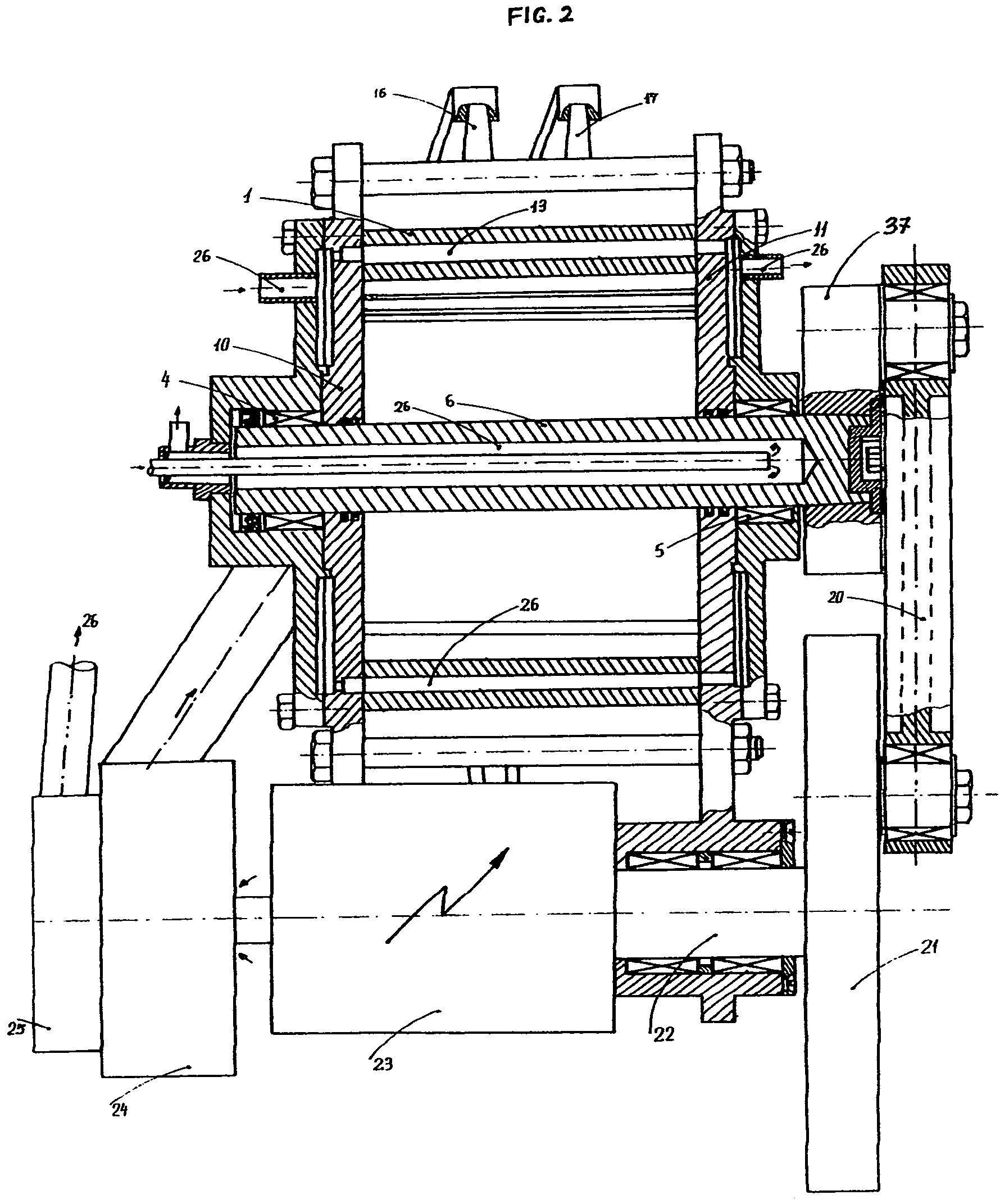
[0054]With reference to FIGS. 15, &20 in the drawings, the essential concept of the present invention and the means by which it is intended to operate may be appreciated. At 1, a double-walled, water-jacketed, longitudinally extending cylindrical casing is shown, in section. The casing may be conveniently made of aluminum, steel or other commonly used materials. The casing is equipped at 2 and 3 with longitudinally extending walls, which can be unitary with, or affixed to the casing 1. A rotary shaft is suitably rotably mounted within the casing upon end plates 10 and 11 for the casing (FIG. 2). The shaft is supported in the casing by commonly known bearing means 4 and 5 for mounting a rotary shaft in a motor, pump, or compressor. The shaft is partially hollow to allow the flow of cooling fluids inside it. Similar to the cylindrical casing the end plates 10&11 are also double-walled to allow coolant to flow freely from the water pump 25 through all the cavities of the cylinder, the ...


PUM


Abstract

A rotatably alternating air or water cooled two-stroke internal combustion engine comprising a cylindrical casing, and a rotor comprising two radially extending vanes affixed to a shaft rotatably mounted within the casing upon two end plates. Two longitudinally extending walls affixed to the casing. Sealing strips provided between said walls, the shaft, the vanes, the casing and the end plates respectively. Working and supercharging interior chambers between the vanes and the walls. The casing and / or the end plates equipped with ports which communicate with the interior chambers, allowing for intake of combustible air-fuel mixture and exhaust thereafter. Ignition means delivering a spark at the end of each working cycle. An extendable and adjustable connecting rod assembly converting the oscillating bi-directional rotary motion of the output shaft into a continuous unidirectional motion of the main shaft. A self lubricating mechanism incorporated into the engine.

Description

[0001]This is a division of application Ser. No. 11 / 176,899 filed Jul. 8, 2005, now U.S. Pat. No. 7,222,601 B1, granted on May 29, 2007.BACKGROUND OF THE INVENTION[0002]This invention relates to a rotatively reciprocating vane internal combustion engine having few moving parts, high efficiency, and a low weight-to-power ratio.[0003]In an age of environmental concerns and waning natural resources, a lightweight, highly efficient, low fuel consumption engine has been vigorously sought.[0004]In the past, attempts have been made to improve on reciprocating piston engines but their inherent complexity and high weight-to-power ratio has proven limiting. Also rotary or Wankel design engines have become relatively highly developed, they still exhibit daunting problems in rotor sealing and cost parameters. For example, the Wankel engine is difficult to manufacture, it has a short life, it has a problem of loosing its lubrication and seizing up. It has poor gas mileage, high oil consumption a...

Claims


Application Information

Patent Timeline
Patent Type & Authority Patents(United States)
IPC IPC(8): F02B53/00F02B75/00F01C1/07F04C2/00F01C1/063F01C1/00F04C18/00F02B53/02F01C9/00
CPCF01C21/04F01C9/002
Inventor KAMENOV, KAMEN GEORGE
Owner KAMENOV KAMEN GEORGE
Why Eureka
Try Eureka