Liquid crystal display apparatus

a liquid crystal display and apparatus technology, applied in the direction of printed circuit non-printed electric components, instruments, color signal processing circuits, etc., can solve the problems of reducing the amount of obstructing the upward flow of air, and large number of tall circuit elements, so as to achieve the effect of increasing the size of the liquid crystal display apparatus

Inactive Publication Date: 2011-06-21
DENSO CORP
View PDF113 Cites 8 Cited by
  • Summary
  • Abstract
  • Description
  • Claims
  • Application Information

AI Technical Summary

Benefits of technology

[0012]In view of the above-described problem, it is an object of the present invention to provide a liquid crystal display apparatus in which adequate airflow can be provided without increasing size of the liquid crystal display apparatus.
[0014]A direction of airflow caused by natural convection due to heat generated by the liquid crystal display apparatus is the same as the vertical direction. Since the first and the second elements having the long projecting length are arranged on the mounting surface approximately in the line in the vertical direction, the airflow easily flows along the mounting surface of the circuit board. Thus, the circuit elements mounted on the mounting surface of the circuit board can be adequately cooled by the airflow without increasing size of the liquid crystal display apparatus.

Problems solved by technology

The number of the tall circuit elements is large and the tall circuit elements obstruct the upward flow of air.
As a result, the amount of the upward flow of air is reduced and the circuit elements mounted on the circuit board 200 cannot be maintained below the maximum operating temperature during the operation of the conventional LCD apparatus.
Therefore, it is difficult to increase the distance between the case and the capacitors 9, 10.

Method used


Image

  • Liquid crystal display apparatus
  • Liquid crystal display apparatus
  • Liquid crystal display apparatus

Examples


first embodiment

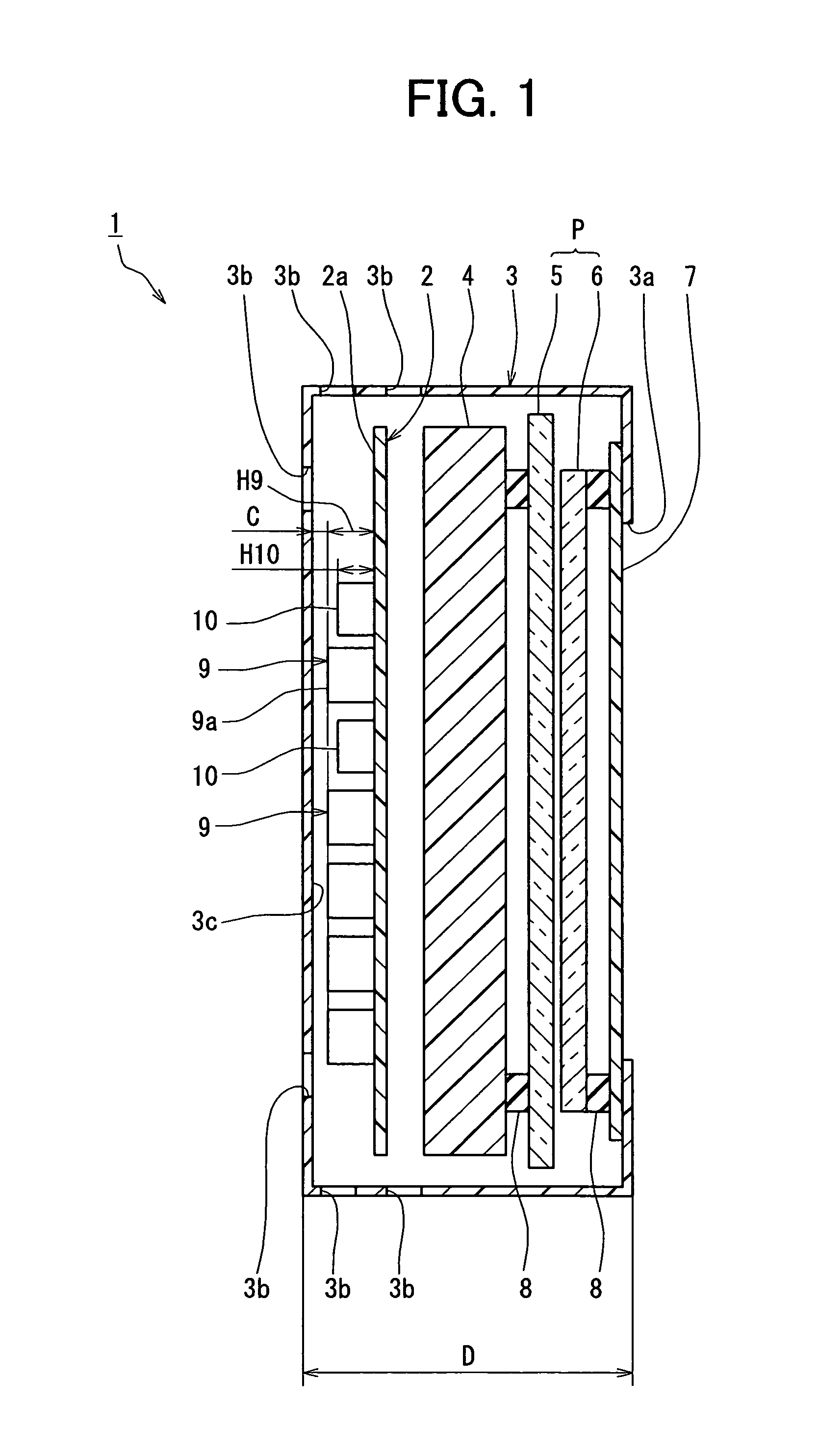
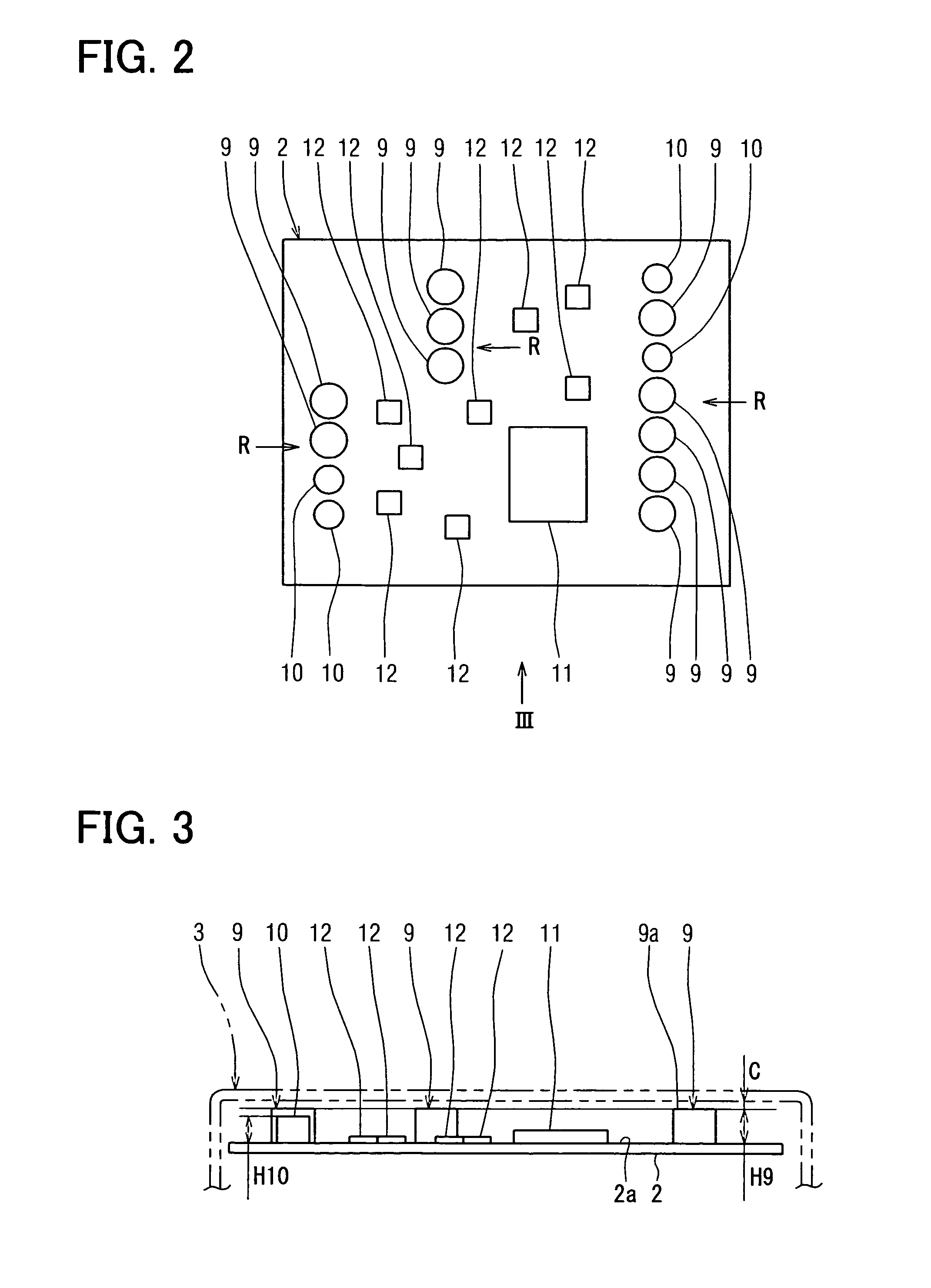
[0024]Referring to FIG. 1, a matrix type liquid crystal display (LCD) apparatus 1 includes a liquid crystal panel P, a printed circuit board 2, a case 3 with an opening 3a and vent holes 3b, and a backlight 4 for illuminating the liquid crystal panel P. The liquid crystal panel P, the printed circuit board 2, and the backlight 4 are housed in the case 3. The LCD apparatus 1 is approximately vertically mounted to a vehicle such that the liquid crystal panel P faces horizontally toward a driver. Accordingly, the circuit board 2 is approximately vertically positioned during normal use of the LCD apparatus 1.

[0025]The liquid crystal panel P has electrode substrates 5, 6 between which antiferroelectric liquid crystals are injected. Polarizing films are attached to the outside of each of the electrode substrates 5, 6. The electrode substrate 5 is constructed such that a color filter, transparent electrodes arranged in lines, and a rubbed film are stacked on one surface of a transparent su...

second embodiment

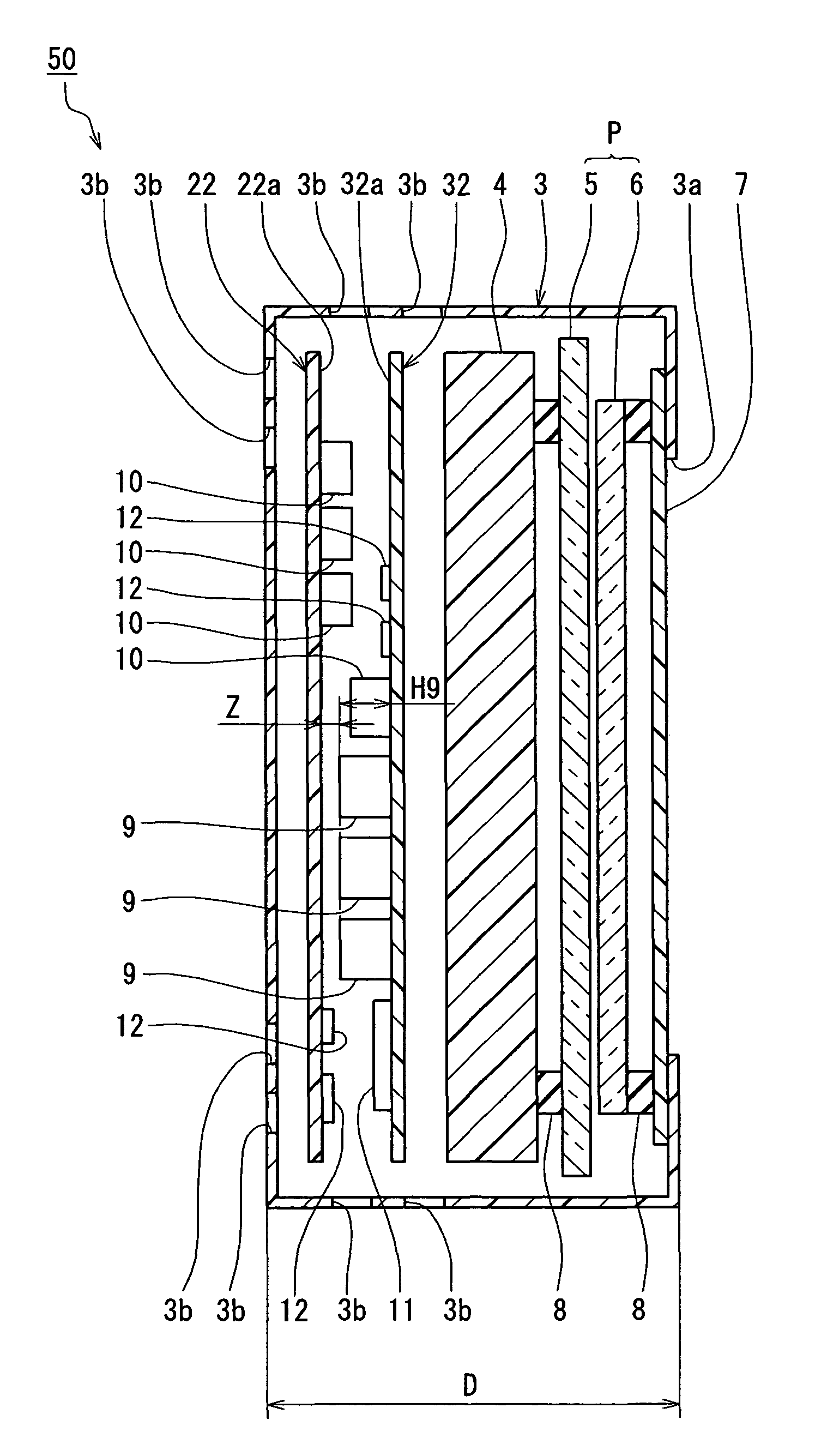
[0050]Referring to FIG. 6, a LCD apparatus 50 according to a second embodiment of the present invention is described. FIG. 6 corresponds to FIG. 1. Whereas the LCD apparatus 1 according to the first embodiment includes one printed circuit board 2, the LCD apparatus 50 includes two printed circuit boards 22, 32.

[0051]The printed circuit board 32 has the capacitors 9, 10, the CPU 11, and the electronic elements 12. The capacitors 9, 10 are arranged in lines on a mounting surface 32a of the printed circuit board 32 such that the capacitors 9, 10 approximately overlap each other in each line when viewed from the vertical direction from the top (bottom) to the bottom (top) of FIG. 6.

[0052]The printed circuit board 22 has the capacitors 10 and the electronic elements 12. The capacitors 10 are arranged in lines on a mounting surface 22a of the printed circuit board 22 such that the capacitors 10 approximately overlap each other in each line when viewed from the vertical direction.

[0053]A s...


PUM


Abstract

A LCD apparatus includes a liquid crystal panel, a circuit board having a mounting surface and circuit elements mounted on the mounting surface to constitute a drive circuit for driving the LCD apparatus, and a case for holding the liquid crystal panel and the circuit board. The circuit board is positioned approximately in a vertical direction during normal use of the LCD apparatus. The circuit elements include a first element having a first projecting length from the mounting surface and a second element having a second projecting length from the mounting surface. The first projecting length is greater than a projecting length of any other element of the circuit elements. The second projecting length is slightly smaller than the first projecting length. The first and the second elements are arranged on the mounting surface approximately in a line in the vertical direction.

Description

CROSS REFERENCE TO RELATED APPLICATION[0001]This application is based on and incorporates herein by reference Japanese Patent Application No. 2005-264282 filed on Sep. 12, 2005.FIELD OF THE INVENTION[0002]The present invention relates to a liquid crystal display apparatus.BACKGROUND OF THE INVENTION[0003]A conventional liquid crystal display (LCD) apparatus, for example, disclosed in JP-H11-38384A, includes a liquid crystal panel, a backlight for illuminating the liquid crystal panel, a circuit board having an electrical circuit for driving the liquid crystal panel. The liquid crystal panel, the backlight, and the circuit board are stacked in that order and housed in a case.[0004]In such a conventional LCD apparatus, a heater heats the liquid crystal panel to its desired operating temperature, thereby increasing the speed of response of the liquid crystal panel. The circuit board includes many circuit elements such as a transistor, diode, and the like. Some of these circuit elements...

Claims


Application Information

Patent Timeline
Patent Type & Authority Patents(United States)
IPC IPC(8): H04N9/74
CPCG02F1/13452H05K1/144H05K1/18H05K2201/064H05K2201/042
Inventor KUROKAWA, KAZUMASAKONDO, YOSHIMISHIBATA, HIROKAZU
Owner DENSO CORP
Why Eureka
Try Eureka