Aesthetic conduit end cap structure having concealed anchor attachments

a technology of anchor attachment and end cap, which is applied in the direction of sewer pipelines, filtration separation, and separation processes, can solve the problems of unsightly appearance of the cover, the screw attachment is not secure, and the cover is exposed to view

Active Publication Date: 2011-10-25
CALIFORNIA FAUCETAB
View PDF56 Cites 68 Cited by
  • Summary
  • Abstract
  • Description
  • Claims
  • Application Information

AI Technical Summary

Benefits of technology

[0007]The present invention provides a novel conduit end cap structure that is secure and aesthetically pleasing. In accordance with the present invention, the end cap of the conduit is provided with anchor supports that allow anchors to be used to securely attach the cap to the conduit, and that are concealed or substantially concealed from plain view squarely at the end cap.
[0008]In one embodiment of the present invention, an aesthetic end cap structure is designed for a drain assembly (e.g., a floor drain assembly). The cap structure comprises a perforated plate, which may be in the form of a strainer, grid, grate, etc. The plate has an external side that is exposed to view when installed, and an internal side that is not exposed to view when installed. One or more anchor supports extend from the internal side of the plate, each providing support for an anchor that is received by an anchor receiving structure on the conduit to securely attach the plate to the conduit near its opening. In one embodiment, the anchor is in the form of a fastener (e.g., a set screw), and the anchor receiving structure is in the form of a channel provided on the inside wall of the conduit opening. The fastener extends into the channel, thereby securely retaining the plate on the conduit to prevent it from dislodging from the conduit end.

Problems solved by technology

However, snap attachments are not secure, and screw fasteners leave an unsightly appearance for covers that are exposed to view.

Method used


Image

  • Aesthetic conduit end cap structure having concealed anchor attachments
  • Aesthetic conduit end cap structure having concealed anchor attachments
  • Aesthetic conduit end cap structure having concealed anchor attachments

Examples


Embodiment Construction

[0020]This invention has been described herein in reference to the drawings. The present description is of the best presently contemplated mode of carrying out the invention. This description is made for the purpose of illustrating the general principles of the invention and should not be taken in a limiting sense. It will be appreciated by those skilled in the art that variations and improvements may be accomplished in view of these teachings without deviating from the scope and spirit of the invention. The scope of the invention is best determined by reference to the appended claims.

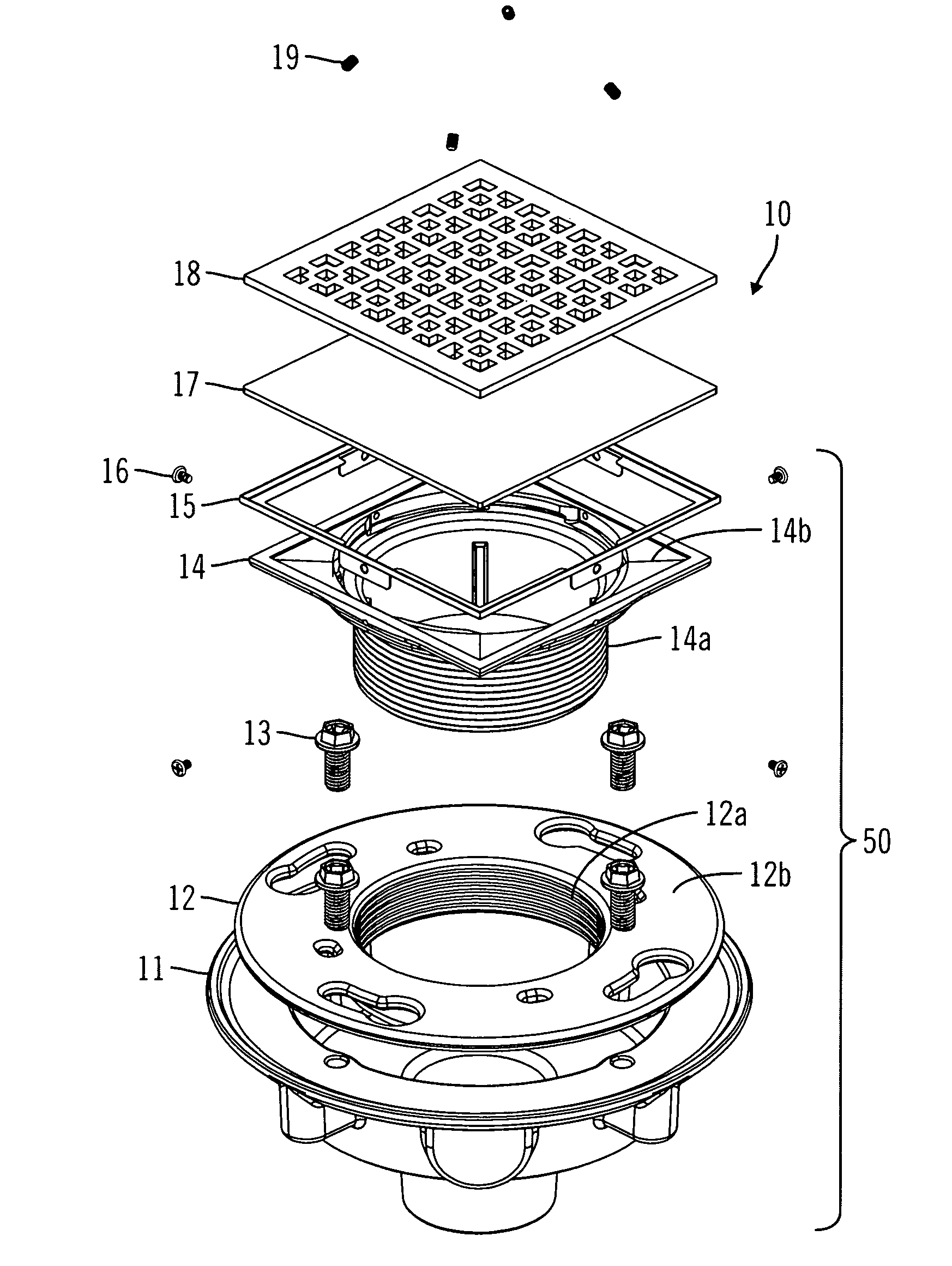
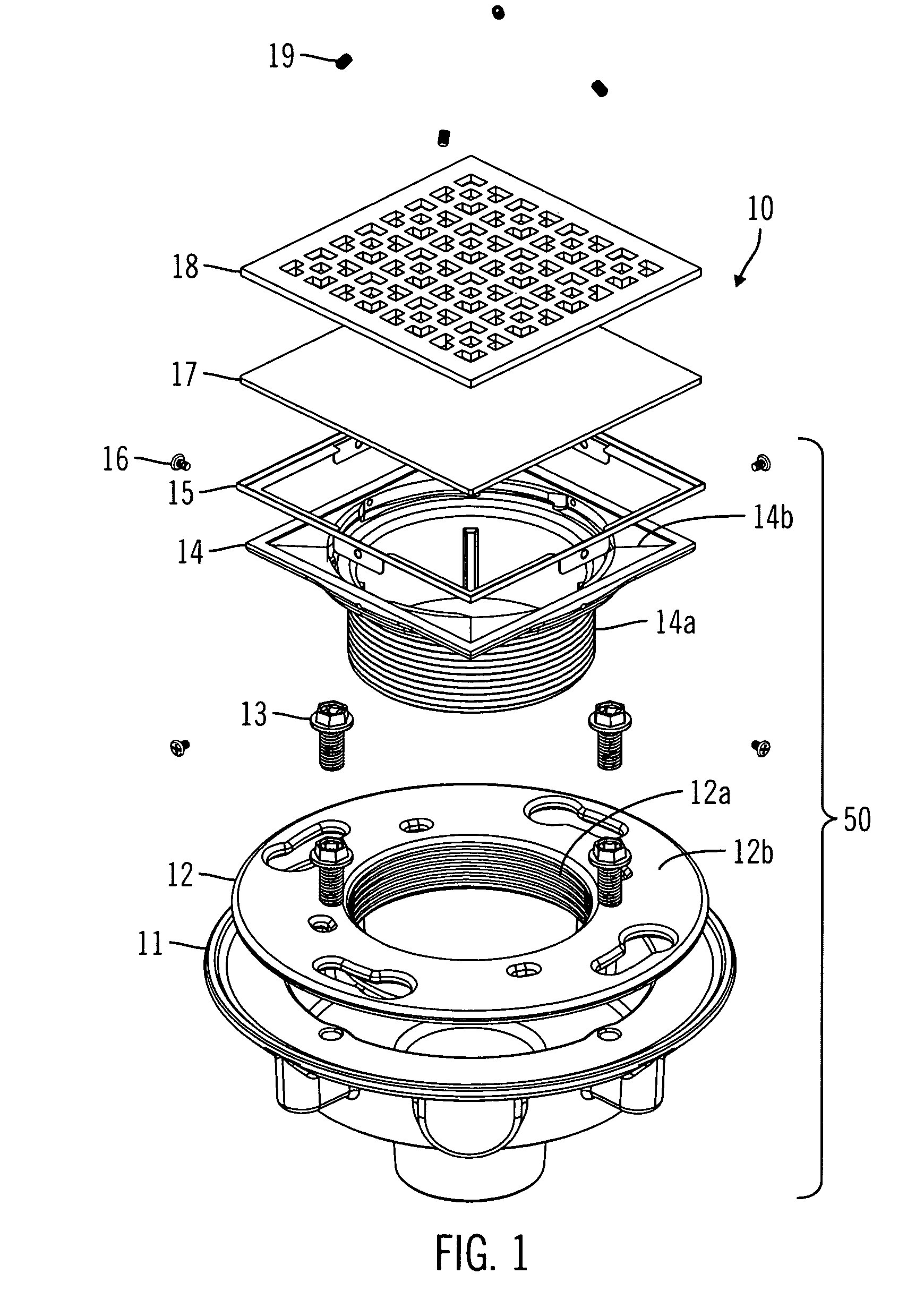
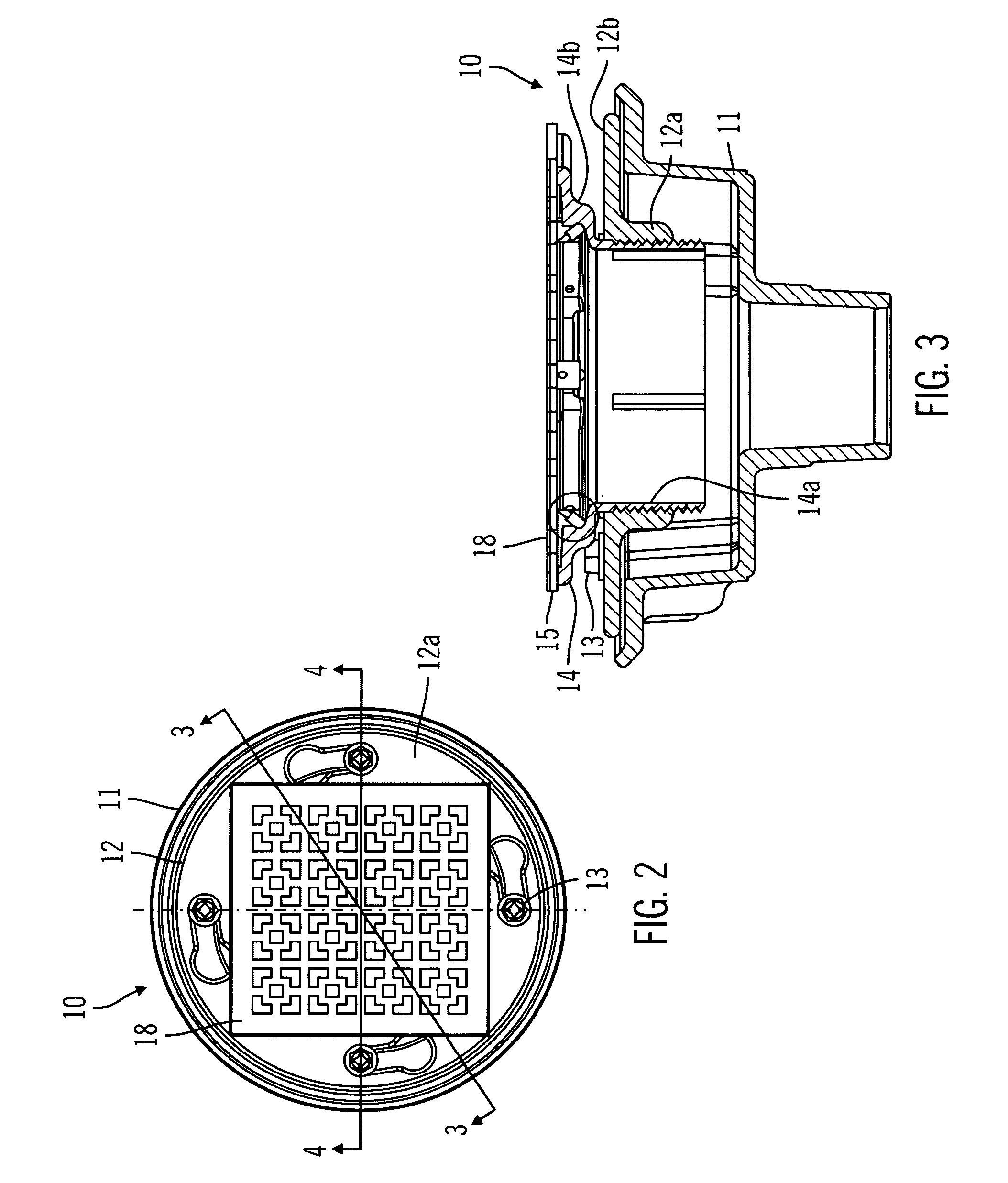
[0021]The present invention provides a novel conduit end cap structure that is secure and aesthetically pleasing. In accordance with the present invention, the end cap of the conduit is provided with anchor supports that allow anchors to be used to securely attach the cap to the conduit but are substantially concealed from plain view squarely at the end cap. By way of illustration, the present inventio...


PUM

PropertyMeasurementUnit
heightaaaaaaaaaa
oblique angleaaaaaaaaaa
structureaaaaaaaaaa

Abstract

A conduit end cap structure (e.g., a floor drain assembly) that is securely attached to the conduit and aesthetically pleasing. The end cap of the conduit comprises a perforated plate. Anchor supports extend from the substantially concealed underside of the plate, each providing support for an anchor that is received by an anchor receiving structure on the conduit to securely attach the plate to the conduit near its opening. The anchor may be in the form of a fastener (e.g., a set screw), and the anchor receiving structure is in the form of a channel provided on the inside wall of the conduit opening. The fastener extends into the channel, thereby securely retaining the plate to prevent it from dislodging from the conduit end.

Description

RELATED CASE[0001]This application claims the priority of U.S. Provisional Patent Application No. 60 / 933,723, filed Jun. 7, 2007, which is fully incorporated by reference as if fully set forth herein.BACKGROUND OF THE INVENTION[0002]1. Field of the Invention[0003]The present invention relates to capping structure at the terminating ends of ducts or conduits (e.g., floor drains), in particular capping plates having substantially concealed anchor attachment structures (e.g., a grid for capping a drain).[0004]2. Description of Related Art[0005]Ducts and conduits in building structures extend and terminate at openings of finished surfaces. These openings are usually covered with a capping plate. For example, a drain pipe terminates at an opening in the shower floor, which is typically covered with a perforated cover (e.g., a strainer, grid, grate, etc.) that allows liquid to flow therethrough but to prevent larger debris from entering the drain pipe. A ventilation duct terminates at an ...

Claims


Application Information

Patent Timeline
Patent Type & Authority Patents(United States)
IPC IPC(8): E03F3/04
CPCE03F5/0407E03F5/06Y10T137/6851E03F2005/066
Inventor SILVERSTEIN, JEFFREYDESBOROUGH, FREDERICK
Owner CALIFORNIA FAUCETAB
Why Eureka
Try Eureka