Lighting systems for producing different beam patterns

a technology of beam pattern and illumination source, which is applied in the field of lighting system, can solve the problems of difficult to achieve the effect of reducing performance, introducing complexity or reducing performance, and requiring a large amount of time and reducing the cost of operation

Inactive Publication Date: 2006-02-23
OPTICAL RES ASSOCS
View PDF6 Cites 117 Cited by
  • Summary
  • Abstract
  • Description
  • Claims
  • Application Information

AI Technical Summary

Benefits of technology

[0043] In other embodiments of the invention, the lighting systems, such as described above, comprise a flashlight, a bike light, an automobile light (e.g. a headlight), a stage light, a studio light, a surgical light, a display case light, a down light, a light for track lighting, a light for architectural lighting, or other devices for providing light. In certain embodiments of the invention, the lighting systems, such as described above, further comprise a housing, and / or assembly, frame, or support structure to form the flashlight, bike light, automobile light (e.g., headlight), stage light, studio light, a surgical light, display case light, down light, light for track lighting, light for architectural lighting, or other devices for providing light. In certain embodiments of the invention, the light source, the diffusing optical element, and the projection optics may be combined with such housing and / or assembly, frame, or support structure to form the flashlight, bike light, automobile light (e.g., headlight), stage light, studio light, surgical light, display case light, down light, light for track lighting, light for architectural lighting, or other devices for providing light. In some embodiments of the invention, the lighting systems, such as described above, may include an electrical power connector, contact, or connection configured to receive power such as electrical power from, e.g., a battery or electrical power line, to power the light source. In some embodiments of the invention, the lighting systems, such as described above, may also include one or more connectors for attachment to mounts, tracks, stands, or supports such as for a stage light, a studio light, a display case light, a down light, a light for track lighting, a light for architectural lighting, or other devices for providing light. In some embodiments of the invention, the lighting systems, such as described above, may also include the mounts, tracks, stands, or supports such as for a stage light, a studio light, a surgical light, a display case light, a down light, a light for track lighting, a light for architectural lighting, or other devices for providing light. In some embodiments of the invention, the light source, diffuser, and projection lens may be included in a module that can be attached to an assembly, a housing or portion thereof, a mount, track, stand, or support, to form, for example, a flashlight, a bike light, an automobile light (e.g., a headlight), a stage light, a studio light, a surgical light, a display case light, a down light, a light for track lighting, a light for architectural lighting, or other devices for providing light. A secure attachment may be provided by, for example, by snap fit, threading, welding, riveting, and may be glued, screwed together, bolted, fastened, latched, or otherwise securely connected. In certain embodiments, where the module includes a solid state light source, the module is referred to herein as a solid state emitter module. In certain embodiments of the invention, the lighting systems, such as described above, are configured to produce an output of at least about 10,000 nits, 100,000 nits, or 1,000,000 nits. Other configurations, designs, methods, and applications are also possible.

Problems solved by technology

Illumination sources with adjustable beam patterns can be difficult to create without introducing complexity or reducing performance.
However, switching out optical elements may be technically challenging, costly, and time consuming.
Using multiple illumination sources can be both expensive to implement and difficult to manage.

Method used


Image

  • Lighting systems for producing different beam patterns
  • Lighting systems for producing different beam patterns
  • Lighting systems for producing different beam patterns

Examples


Embodiment Construction

[0081] Certain embodiments of the invention include lighting systems or assemblies that produce an optical beam. Moreover, in various embodiments, the beam may be altered to provide, for example, a narrow beam or a wide beam.

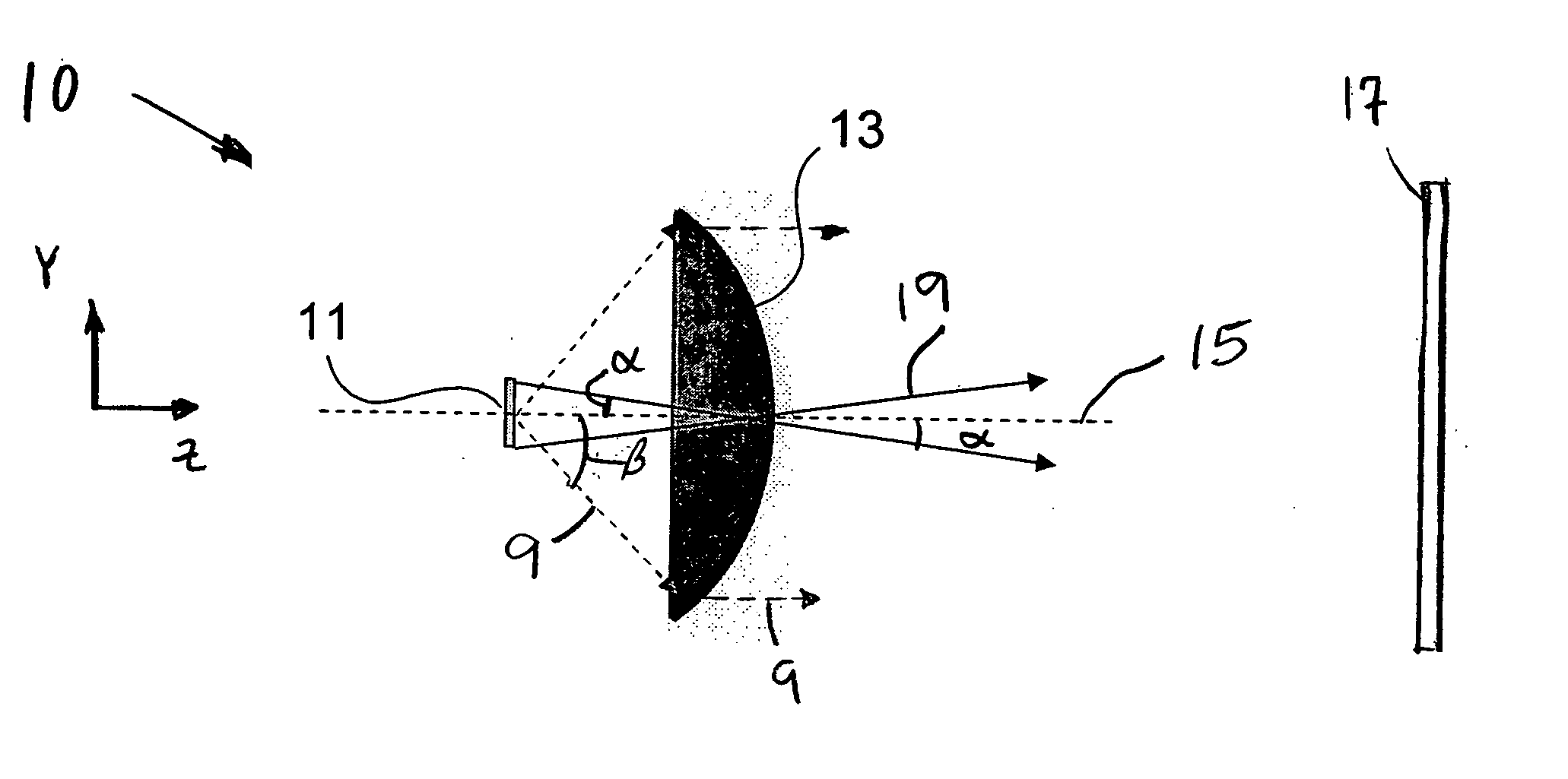
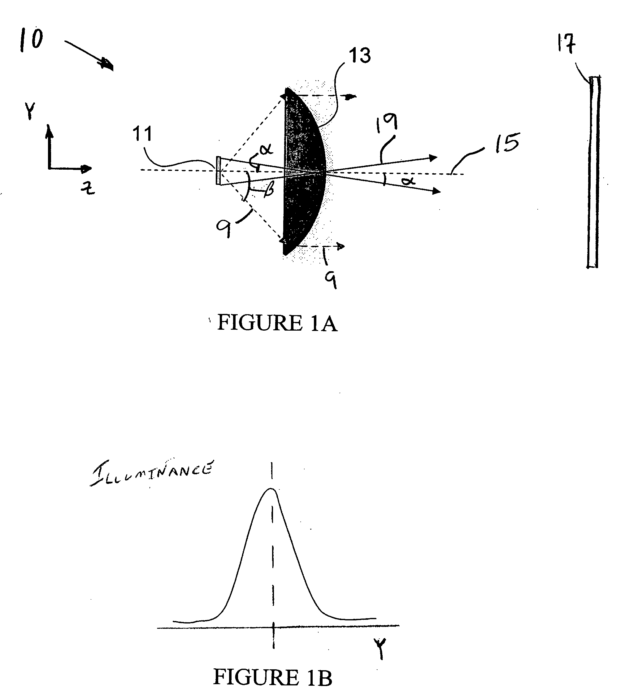
[0082]FIG. 1A schematically illustrates a lighting system 10 comprising a light source 11 and a projection lens 13 aligned along an optical axis 15. The light source 11 is shown as an extended source having finite lateral dimensions. This light source 11 may comprise, for example, an incandescent bulb or a light emitting diode (LED).

[0083] The projection lens 13 comprises a lens having optical power and a corresponding focal length. The light source 11 and the projection lens 13 are positioned with respect to each other such that the light source is imaged by the projection lens. Light in the form of a beam propagates along an optical path from the light source 11 through the projection lens 13. The beam continues along the optical path, which in FIG. 1A is ce...


PUM


Abstract

Various embodiments described herein include lighting systems that produce an optical beam. Moreover, in various embodiments, the beam may be altered to provide, for example, a narrow beam or a wide beam. One such lighting system includes a light source, a diffusing optical element, and a projection lens. The diffusing optical element is disposed between the light source and the projection lens and can be translated to provide zoom capability.

Description

PRIORITY APPLICATIONS [0001] This application claims the benefit of priority under 35 U.S.C. 119(e) to U.S. Provisional Patent Application No. 60 / 603,602, filed Aug. 23, 2004 and entitled “Adjustable Beam Expander” (Attorney Docket OPTRES.043PR), which is incorporated herein by reference in its entirety.BACKGROUND [0002] 1. Field of the Invention [0003] The present teachings relate to lighting systems that can be adjusted to provide different beam patterns. Such lighting systems may be used, for example, for flashlights and other portable lights, bike light, automobile lights, surgical lights, stage lighting, studio lighting, display case lighting, down lights, track lighting, architectural lights, and other applications. [0004] 2. Description of the Related Art [0005] An illumination source can distribute light over a spatial area. The distribution of the light over this range of spatial positions may be referred to as a beam pattern and more particularly, a spatial beam pattern. S...

Claims


Application Information

Patent Timeline
Patent Type & Authority Applications(United States)
IPC IPC(8): G02B6/00
CPCA47F11/10G02B19/0061F21S48/1757F21V5/002F21V13/04F21V14/003F21V14/045F21V14/06F21V14/065F21V17/02F21W2101/10F21W2131/107F21W2131/205F21W2131/405F21W2131/406F21Y2101/02G02B5/02G02B5/0278G02B26/00G02B27/0927G02B27/0944G02B27/0961G02B19/0052G02B19/0028F21S48/1721F21Y2115/10F21S41/322F21S41/635F21W2102/00
Inventor CASSARLY, WILLIAM J.HOUGH, THOMAS A.
Owner OPTICAL RES ASSOCS
Why Eureka
Try Eureka