[0026] Other aspects, features and advantages of this invention will become apparent from the following detailed description when taken in conjunction with the accompanying drawings, which are a part of this disclosure and which illustrate, by way of example, principles of preferred embodiments.
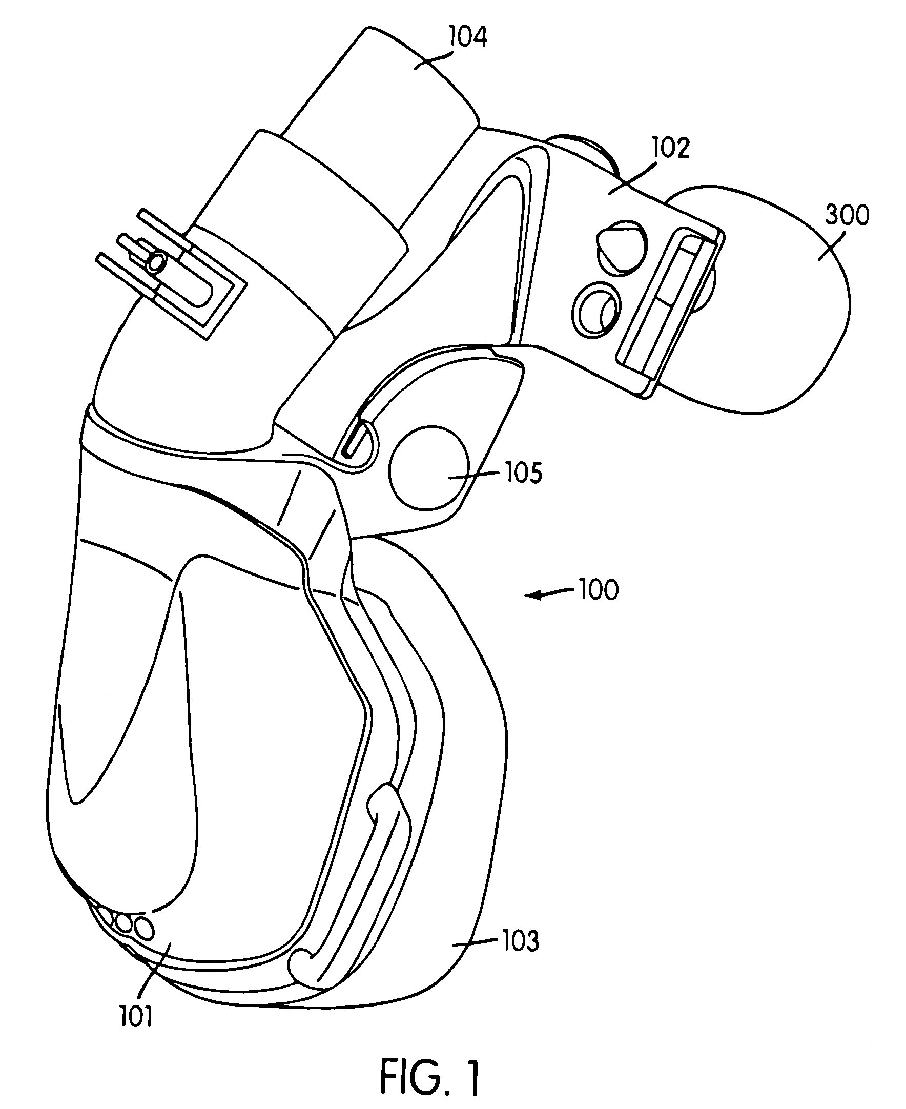
[0027] FIG. 1 is a perspective view of a
respiratory mask and forehead pad according to one embodiment of the present invention;
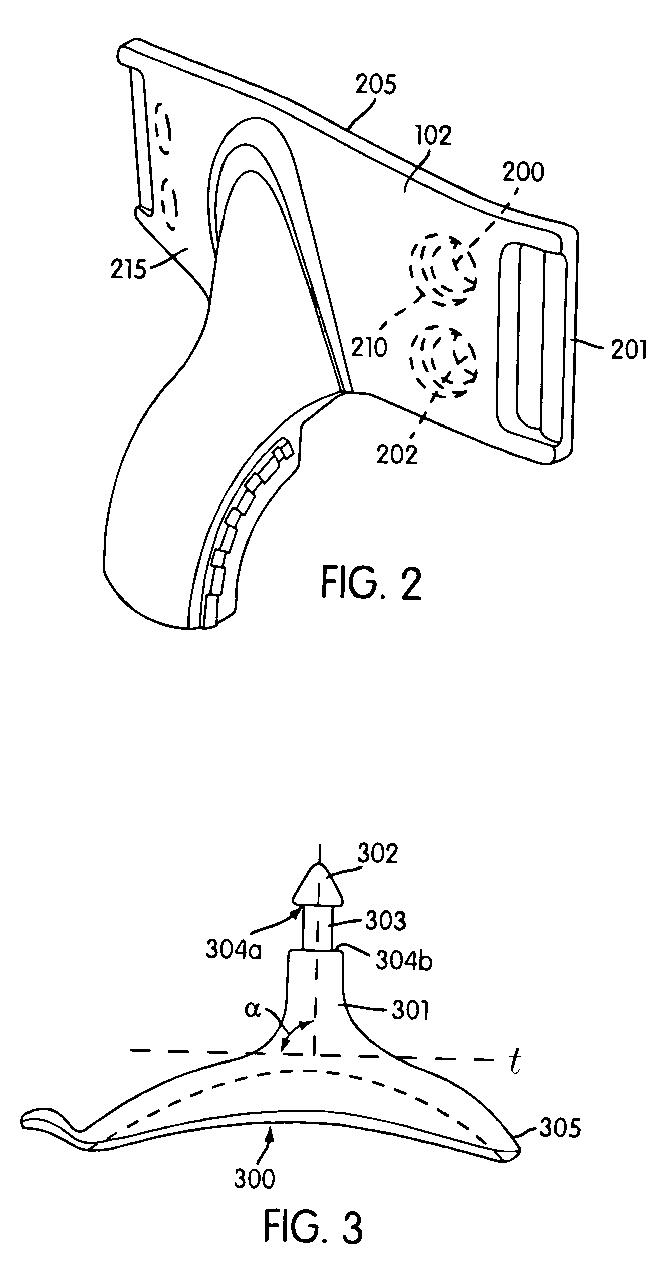
[0028] FIG. 2 is a perspective and enlarged view of the forehead support shown in FIG. 1, without the mask frame and pads;
[0029] FIG. 3 is a perspective view of one embodiment of a forehead pad according to the present invention;
[0030] FIG. 4 is a perspective view of a respiratory mask and forehead pad according to one second embodiment of the present invention;
[0031] FIG. 5 is a perspective view of another embodiment of a forehead pad according to the present invention;
[0032] FIG. 6 is a top view of a forehead support including a pair of forehead pads and a forehead of a user;
[0033] FIG. 7 is a perspective view of the contact surface of one embodiment of a forehead pad showing raised surfaces;
[0034] FIG. 8 is a cross-sectional view of one embodiment of a forehead pad showing a hollowed out region;
[0035] FIG. 9 is a top view of an embodiment of a forehead pad
assembly showing two pads joined by a flexible connector;
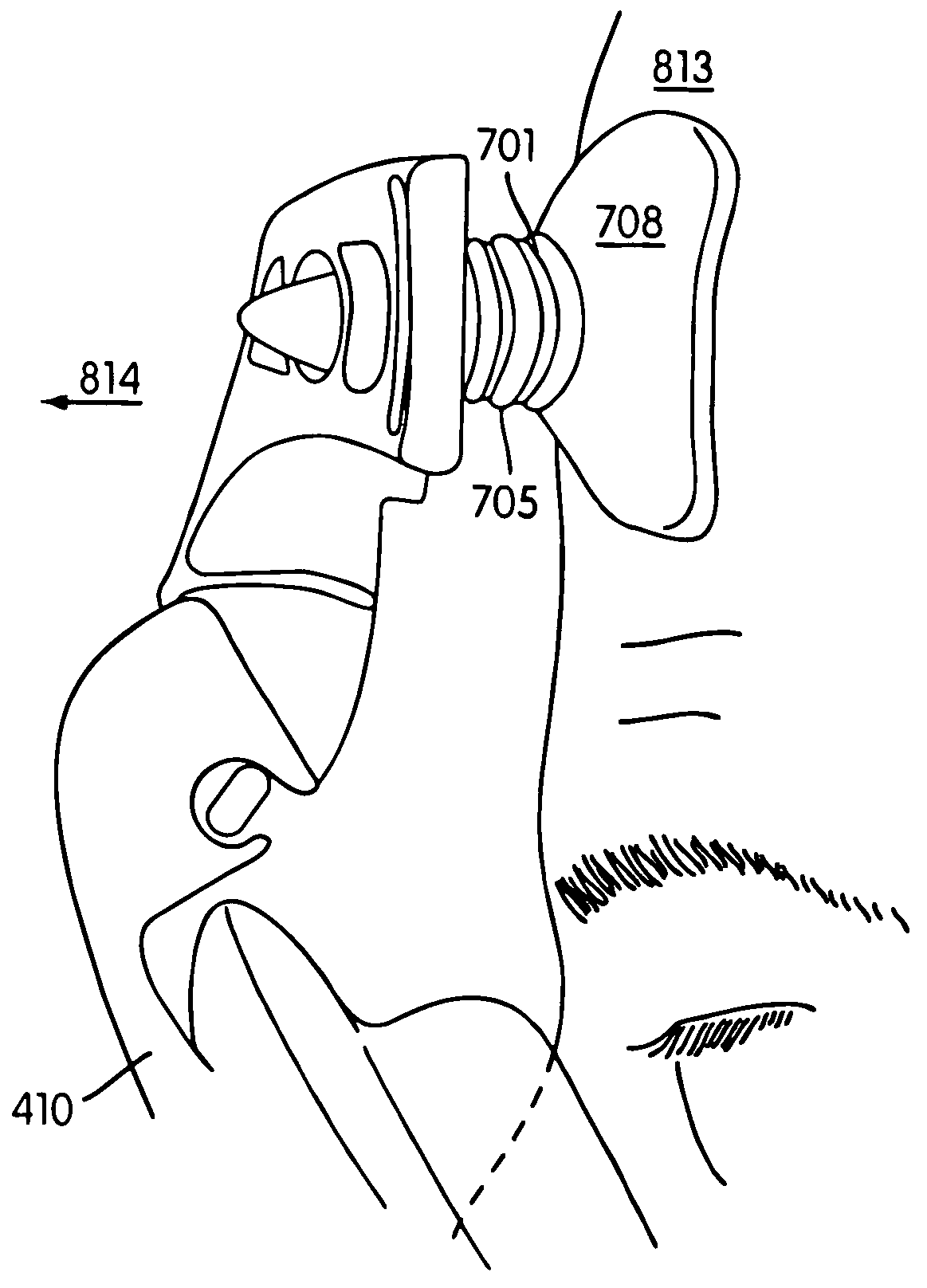
[0036] FIG. 10 is a right side view of one embodiment of a forehead pad in a respiratory mask showing contact with a user;
[0037] FIG. 11 is a cross-sectional view of one embodiment of a forehead pad engaged with one embodiment of a forehead support;
[0038] FIG. 12 is a cross-sectional view of another embodiment of a forehead pad engaged with another embodiment of a forehead support;
[0039] FIG. 13 is a cross-sectional view of another embodiment of a forehead pad engaged with another embodiment of a forehead support;
[0040] FIG. 14 is a cross-sectional view of another embodiment of a forehead pad engaged with another embodiment of a forehead support;
[0041] FIG. 15 is a top view of the embodiment of the forehead support shown in FIG. 14;
[0042] FIG. 16 is a cross-section of a prior art forehead pad;
[0043] FIG. 17 is a cross-section of the forehead pad shown in FIG. 16 in a compressed state;
[0044] FIG. 18 is a cross-section of a prior art forehead pad;
[0045] FIG. 19 is a front view of a prior art forehead support;
[0046] FIG. 20 is a top view of the forehead support shown in FIG. 19;
[0047] FIG. 21 is a side view of another embodiment of a forehead pad according to the present invention;
[0048] FIG. 22 is a bottom view of the embodiment shown in FIG. 21;
[0049] FIG. 23 is a top view of the embodiment shown in FIG. 21;
[0050] FIG. 24 is another side view of the embodiment shown in FIG. 21;
[0051] FIG. 25 is a cross-sectional view of the embodiment shown in FIG. 24 along axis 25-25;
[0052] FIG. 26 is a perspective view of the embodiment shown in FIG. 21;
[0053] FIG. 27 is a perspective view of another embodiment of a forehead support according to the present invention;
[0054] FIG. 28 is an end view of another embodiment of a forehead pad according to the present invention;
[0055] FIG. 29 is a side view of the embodiment shown in FIG. 28;
[0056] FIG. 30 is a perspective view of the embodiment shown in FIG. 28;
[0057] FIG. 31 is a top view of the embodiment shown in FIG. 28;
[0058] FIG. 32 is a rear view of the embodiment shown in FIG. 9;
[0059] FIG. 33 is a top view of the embodiment shown in FIG. 32;
[0059] FIG. 33 is a top view of the embodiment shown in FIG. 32;
[0061] FIG. 35 is an end view of the embodiment shown in FIG. 9;
[0062] FIG. 36 is a cross-sectional view of the embodiment shown in FIG. 35 along axis 36-36;
[0062] FIG. 36 is a cross-sectional view of the embodiment shown in FIG. 35 along axis 36-36;
[0064] FIG. 38 is a rear view of another embodiment a forehead pad according to the present invention;
[0065] FIG. 39 is a top view of the embodiment shown in FIG. 38;
[0066] FIG. 40 is a cross-sectional view of the embodiment shown in FIG. 38 along axis 40-40;
[0067] FIG. 41 is a front view of the embodiment shown in FIG. 38;
[0067] FIG. 41 is a front view of the embodiment shown in FIG. 38;
[0069] FIG. 43 is a cross-sectional view of the embodiment shown in FIG. 42 along axis 43-43;
[0069] FIG. 43 is a cross-sectional view of the embodiment shown in FIG. 42 along axis 43-43;
[0071] FIG. 45 is a cross-sectional view of one embodiment of a forehead pad engaged with one embodiment of a forehead support according to the present invention;
[0072] FIG. 46 is side view of the embodiment shown in FIG. 45;
[0075] FIG. 49 is a top view of the embodiment of the forehead pad engaged with the embodiment of the forehead support shown in FIG. 47 during an intermediate
assembly step;
[0074] FIG. 48 is a top view of the embodiment of the forehead pad and the embodiment of the forehead support shown in FIG. 47;
[0075] FIG. 49 is a top view of the embodiment of the forehead pad engaged with the embodiment of the forehead support shown in FIG. 47 during an intermediate assembly step;
[0076] FIG. 50 is a front view of a prior art forehead pad;
[0077] FIG. 51 is a top view of the forehead pad shown in FIG. 50;
[0079] FIG. 53 is a left view of the forehead pad shown in FIG. 50;
[0079] FIG. 53 is a left view of the forehead pad shown in FIG. 50;
[0080] FIG. 54 is a top view of a prior art forehead pad;
[0081] FIG. 55 is a perspective view of the forehead pad shown in FIG. 55;
[0082] FIG. 56 is a top view of a prior art forehead support;
[0084] FIG. 58 is a top view of another embodiment of a forehead pad according to the present invention;
[0084] FIG. 58 is a top view of another embodiment of a forehead pad according to the present invention;
[0084] FIG. 58 is a top view of another embodiment of a forehead pad according to the present invention;
[0086] FIG. 60 is a rear perspective view of the forehead pad shown in FIG. 59;
[0087] FIG. 61 is a cross-sectional view of the forehead pad shown in FIG. 59 along the
minor axis;
[0087] FIG. 61 is a cross-sectional view of the forehead pad shown in FIG. 59 along the
minor axis;
[0089] FIG. 63 is a perspective view of another embodiment of a forehead pad according to the present invention;
[0090] FIG. 64 is a cross-sectional view of another embodiment of a forehead pad according to the present invention;
[0091] FIG. 65 is a cross-sectional view of another embodiment of a forehead pad according to the present invention;
[0092] FIG. 66 is a cross-sectional view of another embodiment of a forehead pad according to the present invention;
[0093] FIG. 67 is a partial cross-sectional view another embodiment of a forehead pad according to the present invention;
[0094] FIG. 68 shows an embodiment of a forehead pad according to the present invention flexed in a first direction;
[0095] FIG. 69 shows an embodiment of a forehead pad according to the present invention flexed in a second direction;
[0096] FIG. 70 shows an embodiment of a forehead pad according to the present invention flexed in a third direction; and
[0097] FIG. 71 shows an embodiment of a forehead pad according to the present invention flexed in a fourth direction.
[0098] FIG. 1 shows an example of a respiratory mask assembly 100. The mask assembly includes a frame portion 101, a forehead support 102, and a forehead pad 300. The mask is adapted to fasten securely and comfortably to a user's face. In particular, the mask assembly 100 comprises a seal-forming region 103 that covers the user's
nose and / or mouth and a contains opening 104 to which an air delivery tube can be attached. Air or
oxygen flows through the opening 104 under
positive pressure.
[0099] The forehead support 102 is advantageously connected to the frame portion 101 of the mask assembly 100, e.g., by a pivot device 105, which can be adjusted to allow the forehead support 102 to the accommodate the configuration of a user's face. The forehead support 102 is preferably made from a
thermoplastic material. One embodiment of a forehead support is shown in greater detail in FIG. 2.
[0100] The forehead support 102 can be configured to be essentially straight or it can be curved. The essential straight embodiment is shown in FIG. 2. In the case where the forehead support is curved, the curvature generally follows the curvature of the user's forehead. While this is the most likely structure, it is within the scope of the present invention to use a forehead support 102 that has the opposite curvature, or any combination thereof.
[0101] The forehead support 102 can be provided with one or more openings. These openings can be adapted to serve numerous purposes including points of connection to the mask frame, points of connection to any another
support surface, points of connection 201 for straps to secure the mask to the user, and apertures 202 for a forehead pad.
[0102] In a preferred embodiment of the forehead support 102, the apertures 202 are designed to receive a head of the forehead pad 300. The apertures 202 can be disposed about the forehead support 102 in a manner to allow a user to adjust the position of the forehead pad 300. The apertures 202 are also designed to allow a user to attach the forehead pad 300 securely to the forehead support 102. In a preferred embodiment, the apertures 202 designed to allow a user to attach the forehead pad 300 securely and reversibly to the forehead support 102.


