
Medical implant device

a technology of medical implants and implants, applied in the field of medical implants, can solve the problems of affecting the treatment of patients, and affecting the treatment effect, and achieve the effect of facilitating the removal of the implant devi

Inactive Publication Date: 2007-08-23
PHASE ONE MEDICAL
View PDF24 Cites 117 Cited by
  • Summary
  • Abstract
  • Description
  • Claims
  • Application Information

AI Technical Summary

Benefits of technology

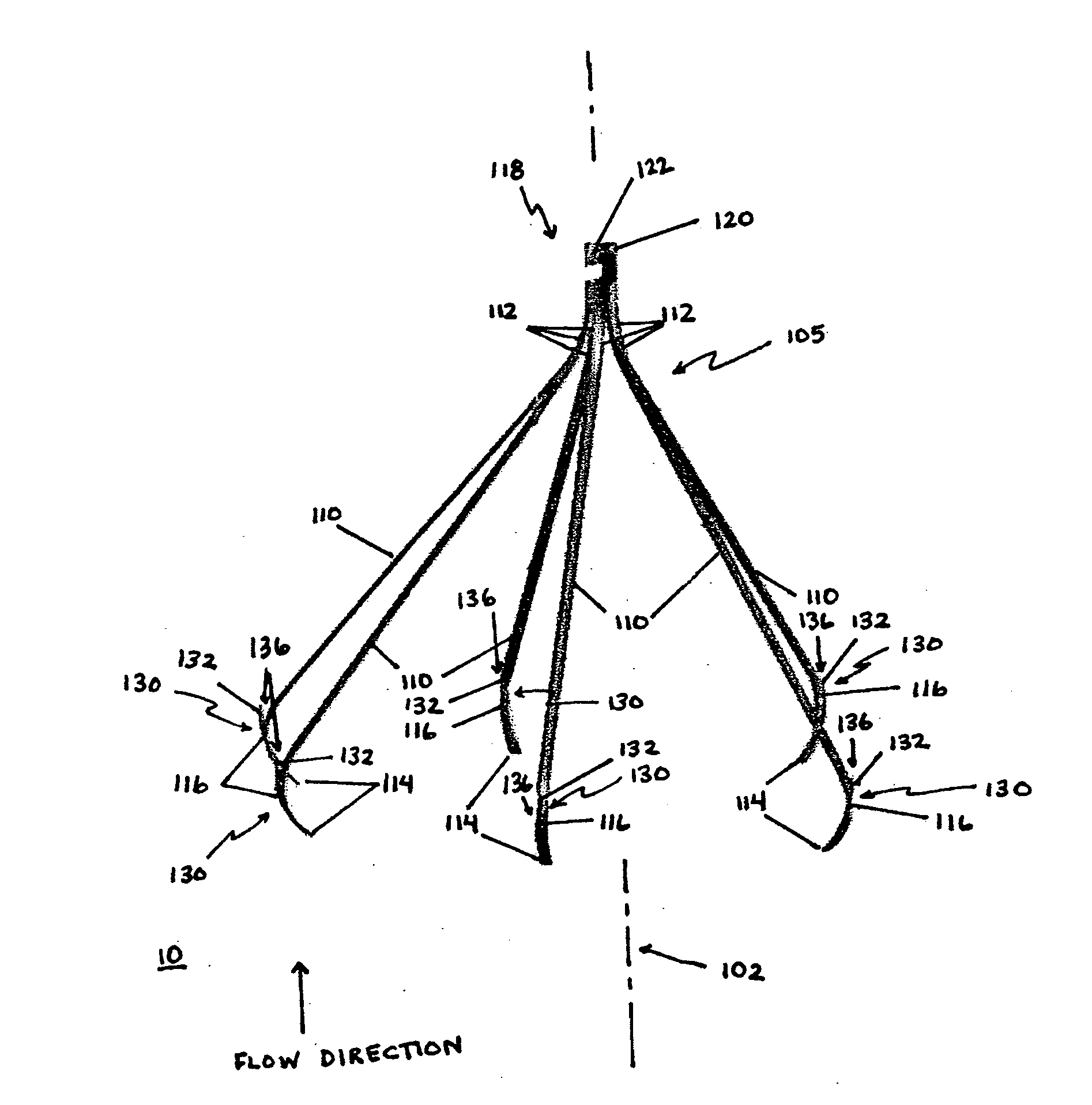
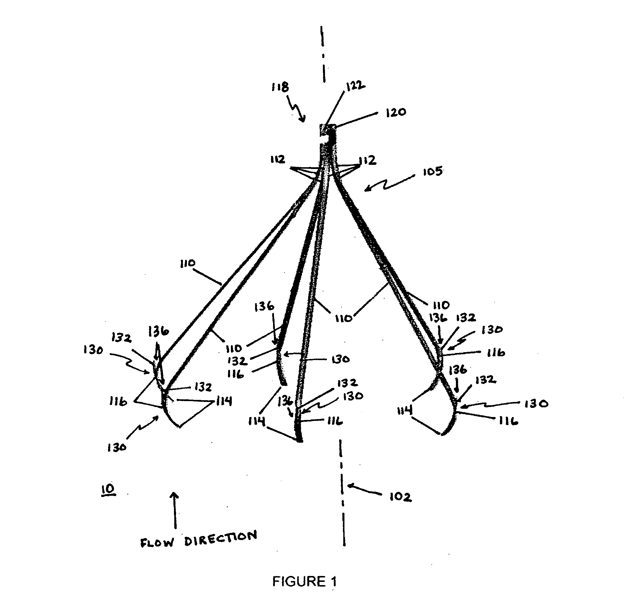
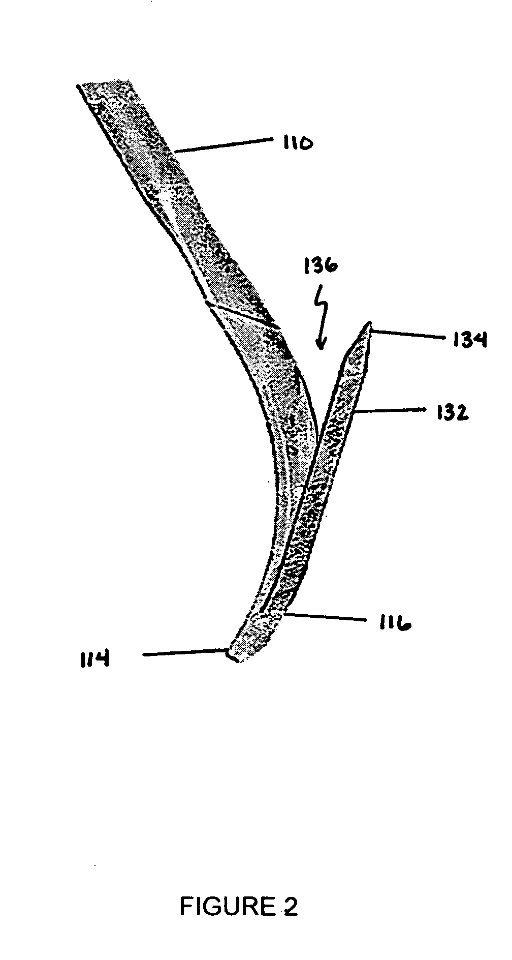
[0018]The present invention provides secure attachment and proper orientation of an implant device in a passageway in a body, while also facilitating removal of the implant device without causing damage to the passageway. As such, the present invention overcomes the shortcomings of, and provides advantages over, the known techniques described above. For instance, with the attachment mechanism of the present invention, the implant device can advantageously be used with a removable tether to permit conversion of the implant device from a temporary to an optional implant device, which may remain in the passageway indefinitely or be removed at a later time.

Problems solved by technology

In particular, major surgery or severe trauma can increase the risk of VTE because blood clots are more likely to form.
PE involves a clot that has traveled to the lung, where it may cause death in a short period of time if it goes untreated.
However, the diagnosis is missed in 70% of those patients.
Obese patients undergoing weight loss surgery (Bariatric) are at substantial risk for developing thromboembolic disease.
PE is a leading cause of death following bariatric surgery for morbid obesity.
Although anticoagulation is effective in preventing PE, many patients go on to experience post-thrombotic syndrome, which is a chronic sequelae of DVT, with resultant valvular insufficiency of the lower extremity.
Despite recent advancements, however, achieving effective deployment and positioning of such devices remains a challenge.
Moreover, even when a device has been successfully implanted, keeping the implanted device in the desired position for an extended period of time presents an even greater challenge.
Devices that are specifically designed for temporary implantation are often difficult to keep in position, because the methods by which they are held in place are purposely weak in order to permit subsequent removal.
Unfortunately, changes in the dimensions of the body vessel or passageway or variations in the flow or pressure of blood or other fluids therethrough can cause the medical implant to migrate and change position.
Locking an implant device in place with embedded hooks may be acceptable for a permanent implant, but rigid hooks are not a viable option if the medical implant device is to be removed after several weeks or months.
Thus, there can be instances where one or more hooks fail to properly engage the wall of a body vessel or passageway.
These systems, disadvantageously, require the use of a delivery tube for each anchor and a delivery mechanism for holding the medical implant device in position while ejecting each anchor from a delivery tube and positively propelling the anchor through the wall of the vessel or passageway.
In particular, patients who are at a one-time temporary risk of pulmonary embolism should receive a vena cava filter, but it is often clinically difficult to justify placement of a permanent filter due to the associated long-term complications.
In some cases, however, the filter cannot be removed without causing significant vessel wall injury, if the filter has become tilted or the tip becomes incorporated into tissue.
However, such devices have been largely unsuccessful.
Tethered filters have failed clinically and commercially for a variety of adverse events.
Such systems suffer from an adverse event known as migration, which is caused by buckling of the tether when the device becomes loaded with blood clots.
Because the tether remains attached to the device, the device cannot be converted into a permanent filter and left in place.
This inability to convert the filter to a permanent implant after the temporary indication period presents a serious dilemma.

Method used


Image

  • Medical implant device
  • Medical implant device
  • Medical implant device

Examples


Embodiment Construction

[0039]The present invention overcomes shortcomings of the known devices described above by providing improved deployment of an implant device that is secured to a vessel, or passageway, in a body. The present invention provides an attachment mechanism that permits stable and secure positioning of an implant device while also permitting easy removal without damaging the passageway. The present invention also provides a tether that works in cooperation with the attachment mechanism to facilitate removal of the implant device after an indicated period. The tether is removable from the implant device to convert the implant device from a temporary device into an optional device, which can remain permanently or be removed at a later time. Moreover, the present invention provides a centering mechanism to ensure that the implant device is properly oriented within the passageway when deployed. These, and other, aspects of the present invention are provided in further detail below.

[0040]While...


PUM


Abstract

An improved implant device is deployed a vessel, or passageway, in a body with an attachment mechanism that permits stable and secure positioning of an implant device while also permitting easy removal without damaging the vessel. In particular, clip-like structures are used to engage the wall of the passageway. A tether that works in cooperation with the attachment mechanism may be used to facilitate removal of the implant device after an indicated period. The tether is removable from the implant device to convert the implant device into another configuration, which can remain permanently or be removed at a later time. Moreover, a centering mechanism may be employed to ensure that the implant device is properly oriented within the passageway when deployed.

Description

CROSS REFERENCE TO RELATED APPLICATIONS[0001]This application claims priority to U.S. Provisional Application No. 60 / 775,355 filed Feb. 22, 2006, the contents of which are incorporated herein by reference.BACKGROUND OF THE INVENTION[0002]1. Field of the Invention[0003]The present invention generally relates to the deployment of a medical implant device in a body passageway, and more particularly to the deployment of medical implant devices with an attachment mechanism which removably attaches the implant device to the wall of the body passageway.[0004]2. Description of Related Art[0005]Venous Thromboembolic Disease (VTE) is a disease where a blood clot forms in a blood vessel and blocks the blood flow. In particular, major surgery or severe trauma can increase the risk of VTE because blood clots are more likely to form. In some cases, the clot travels to other sites in the body, an occurrence known as an embolism. VTE includes deep venous thrombosis (DVT) and pulmonary embolism (PE)...

Claims


Application Information

Patent Timeline
Patent Type & Authority Applications(United States)
IPC IPC(8): A61M29/00
CPCA61F2/01A61F2002/011A61F2230/008A61F2230/005A61F2230/0067A61F2002/016A61F2/0103A61F2/0105A61F2/011
Inventor RAVENSCROFT, ADRIANYANG, YIMIN
Owner PHASE ONE MEDICAL
Learn More