Spring retained end effector contact pad

a contact pad and end effector technology, applied in the field of composite structures with wear resistance, can solve the problems of affecting the service life of the end effector, and requiring replacement of the entire end effector, so as to reduce the dispersion of particulate matter and restrict the movement of the contact pad

Active Publication Date: 2014-10-21
VARIAN SEMICON EQUIP ASSOC INC
View PDF16 Cites 395 Cited by
  • Summary
  • Abstract
  • Description
  • Claims
  • Application Information

AI Technical Summary

Benefits of technology

[0006]In view of the foregoing, it would be advantageous to provide a composite end effector having material-contacting portions that are securely attached to a non-material-contacting portion. It would further be advantageous to provide such an end effector wherein the material-contacting portions may be easily removed from the non-material-contacting portion and replaced. It would also be advantageous to provide such an end effector wherein the arrangement for attaching the material-contacting portions to the non-material-contacting portion permits relative thermal expansion and contraction without loosening, and without damaging the end effector. It would further be advantageous to provide such an end effector that mitigates the dispersion of particulate matter.
[0007]An exemplary end effector in accordance with the present disclosure may include an end effector body, a contact pad pocket formed in the end effector body, a spring retaining pocket formed in the end effector body adjacent the contact pad pocket and extending to an edge of the end effector body, and a pair of through-holes extending from the spring retaining pocket to the contact pad pocket. The end effector may further include a contact pad seated within the contact pad pocket, the contact pad having at least one retaining channel formed therein, and a retaining spring having a pair of retaining arms extending from the retaining spring pocket through the through-holes and into the contact pad pocket. The retaining arms may extend at least partially into the at least one retaining channel of the contact pad and may thereby restrict movement of the contact pad.

Problems solved by technology

One problem associated with such a construction is that when the substrate-contacting portions of such end effectors become excessively worn or contaminated from use, the entire end effector must be replaced.
Such replacement can be expensive as well as wasteful, since the non-material-contacting portions of the end effector may exhibit little or no wear at the time of replacement.
During use, only the ceramic contact pads contact with hot substrates and thus experience wear over time.
For example, the low thermal expansion and low tensile strength properties of ceramics relative to metals makes it difficult to achieve a secure, rigid connection between the two materials as is required for the construction of a composite end effector.
Each of these fastening arrangements, however, exhibits particular deficiencies.
For example, threaded fasteners can impart stresses on ceramic contact pads during thermal cycling, which may result in cracking of the contact pads.
Threaded fasteners may also become loose over time due to vibrations and / or thermal cycling.
Press-fit pads typically cannot be made from ceramic are difficult to remove when replacement become necessary.
Such particles can rain down on other silicon wafers which can be detrimental to their quality.

Method used


Image

  • Spring retained end effector contact pad
  • Spring retained end effector contact pad
  • Spring retained end effector contact pad

Examples


Embodiment Construction

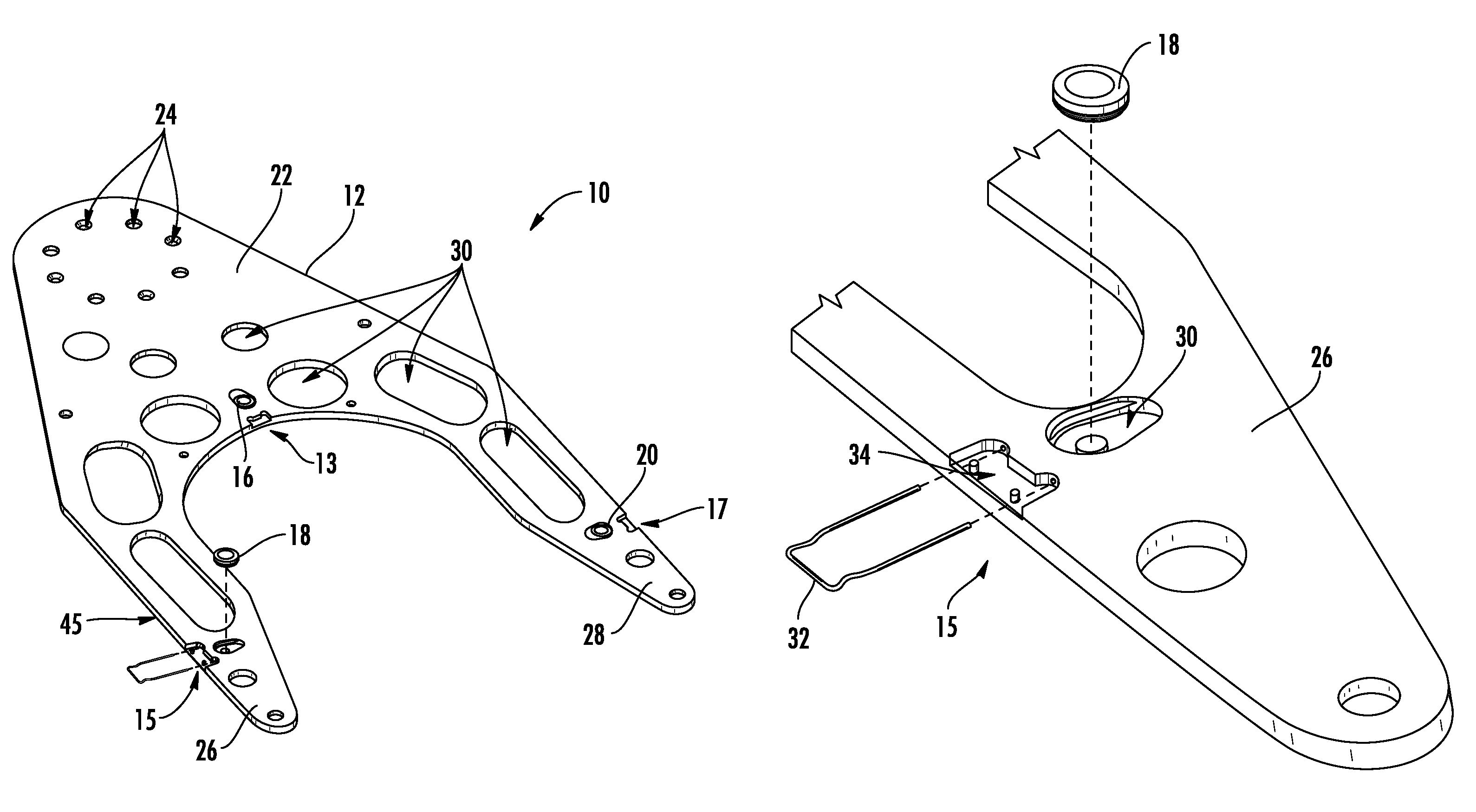
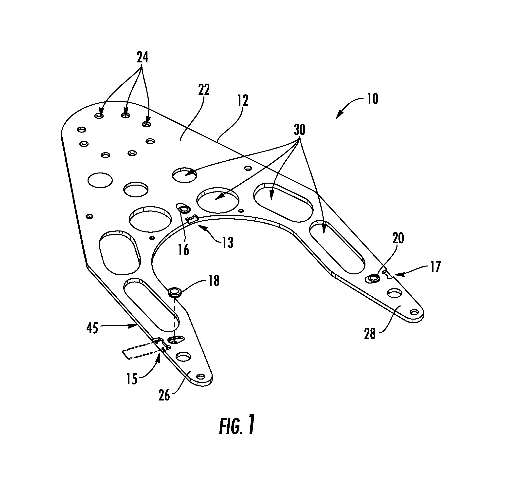
[0017]An improved composite end effector in accordance with the present disclosure will now be described more fully hereinafter with reference to the accompanying drawings, in which preferred embodiments of the invention are shown. The disclosed end effector, however, may be embodied in many different forms and should not be construed as being limited to the embodiments set forth herein. Rather, these embodiments are provided so that this disclosure will be thorough and complete, and will fully convey the scope of the invention to those skilled in the art. In the drawings, like numbers refer to like elements throughout.

[0018]FIG. 1 illustrates an exemplary embodiment of a composite end effector 10 in accordance with the present disclosure. For the sake of convenience and clarity, terms such as “front,”“rear,”“top,”“bottom,”“right,”“left,”“up,”“down,”“inwardly,”“outwardly,”“lateral” and “longitudinal” will be used herein to describe the relative placement and orientation of component...


PUM


Abstract

An end effector is disclosed for use in substrate processing. The end effector includes a effector body portion, a contact pad pocket formed in the end effector body, a spring retaining pocket formed in the end effector body adjacent the contact pad pocket and extending to an edge of the end effector body, and a pair of through-holes extending from the spring retaining pocket to the contact pad pocket. The end effector can include a contact pad seated within the contact pad pocket, the contact pad having at least one retaining channel formed therein, and a retaining spring having a pair of retaining arms extending from the retaining spring pocket through the through-holes and into the contact pad pocket. The retaining arms may extend at least partially into the at least one retaining channel of the contact pad and may thereby restrict movement of the contact pad.

Description

FIELD OF THE DISCLOSURE[0001]The disclosure relates generally to wear-resistant composite structures, and more particularly to a composite end effector having a retaining spring for removably attaching a removable contact pad to the end effector.BACKGROUND OF THE DISCLOSURE[0002]During production, substrates are often handled by robotic arms that are equipped with specialized tools, or “end effectors,” that are adapted for lifting and moving the substrates. Since substrates can reach high temperatures during processing (e.g., >500° C.), end effectors generally are made from materials that exhibit good thermal stability and wear resistance at high temperatures. Examples of such materials include alumina, zirconia, silicon nitride, silicon carbide, and other ceramics.[0003]Conventional high-temperature end effectors are often made entirely from ceramic. One problem associated with such a construction is that when the substrate-contacting portions of such end effectors become excess...

Claims


Application Information

Patent Timeline
Patent Type & Authority Patents(United States)
IPC IPC(8): B65G49/07B25J15/00
CPCB25J15/0014Y10S414/141Y10S294/902H01L21/68707
Inventor SCHRAMEYER, MICHAEL, A.
Owner VARIAN SEMICON EQUIP ASSOC INC
Why Eureka
Try Eureka