Pulsed arc welding method

a welding method and arc welding technology, applied in the direction of arc welding apparatus, welding apparatus, manufacturing tools, etc., can solve the problems of excessive generation of spatters and fumes, high cost of arc gas, irregular droplet transfer, etc., and achieve the effect of improving the stability of the welding arc, reducing the generation rate of fumes, and facilitating maintenan

Active Publication Date: 2007-09-13
KOBE STEEL LTD
View PDF5 Cites 54 Cited by
  • Summary
  • Abstract
  • Description
  • Claims
  • Application Information

AI Technical Summary

Benefits of technology

[0026]In the arc welding of a consumable electrode type according to the invention wherein carbon dioxide gas alone or a mixed gas made mainly of carbon dioxide gas is used, one pulse -one droplet transfer can be achieved in a very highly regular manner. On comparison with prior art methods, stabilization of a welding arc is improved, large-particle spatters and fume generation rates can be remarkably reduced and, at the same time, particulate spatters due to scattering in a constricted portion at the wire tip during the release of a droplet and due to scattering of a remaining molten pool on a wire after the release of a droplet can be significantly reduced. If the distance between a chip and a base metal varies, an arc length can be readily kept at a given level by controlling pulse parameters, within ranges not disturbing the one pulse-one droplet transfer.

Problems solved by technology

However, since Ar gas is costly, compared with carbon dioxide gas, carbon dioxide gas alone or a mixed gas made mainly of carbon dioxide gas has been predominantly used as a shield gas for carrying out welding operations in general.
This undesirably leads to the problems in that short-circuiting with a base metal and arc break are liable to occur, droplet transfer becomes irregular, and spatters and fumes are excessively generated.
In these conventional methods, however, there is a problem that the droplet is released during the pulse peak period, causing particulate spatters to be generated in large amounts due to scattering in the constricted portion of the wire tip when the droplet is released and due to scattering of a molten pool remaining on the wire after the droplet is released therefrom.
Therefore, a significant reduction of spatters cannot be attained by simply applying high frequency pulses continuously as in these conventional methods because the release time differs in every release timing, and the intervals of the droplet transfer vary within a range of about 15 to 25 milliseconds.
That is, in order to control a wire melting rate, a pulse frequency has to be greatly changed, but this only disturbs regularity of droplet transfer.
Accordingly, in the case of weaving a groove where the distance between a chip and a base metal varies within about ±5 mm from a standard condition, a difficulty is involved in keeping a stable arc.
If a pulse peak current permitting the release of a droplet is set, a molten metal remaining on a wire after the release of a droplet scatters by a great arc force when a subsequent pulse peak after the release is applied and generates a lot of large-particle spatters.
However, when a first pulse period and a first base period are set short according to an increase in the wire feed quantity, in a cutoff layer under an electromagnetic pinch force by the second pulse, a droplet at a wire tip is not shaped in a satisfactory manner and the electromagnetic pinch force is not effectively applied.
In consequence, regularity of one pulse group-one droplet transfer cannot be kept, and large-particle spatters are generated.

Method used


Image

  • Pulsed arc welding method
  • Pulsed arc welding method
  • Pulsed arc welding method

Examples


examples

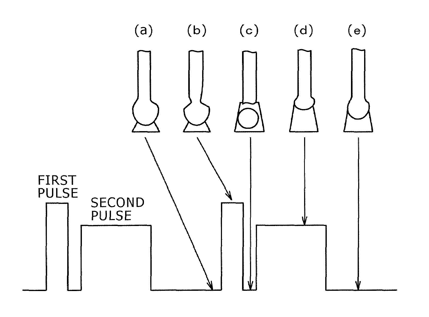
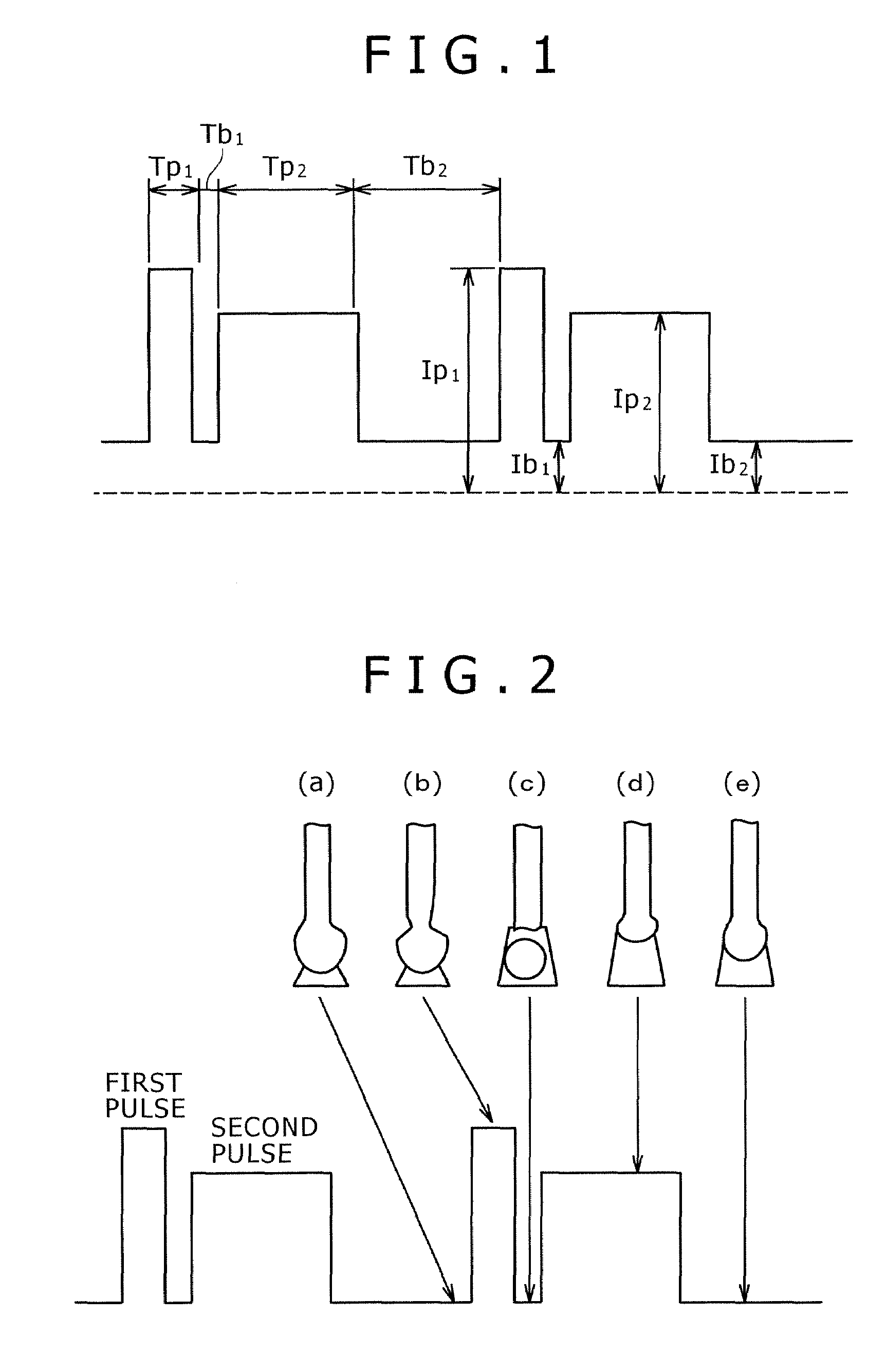
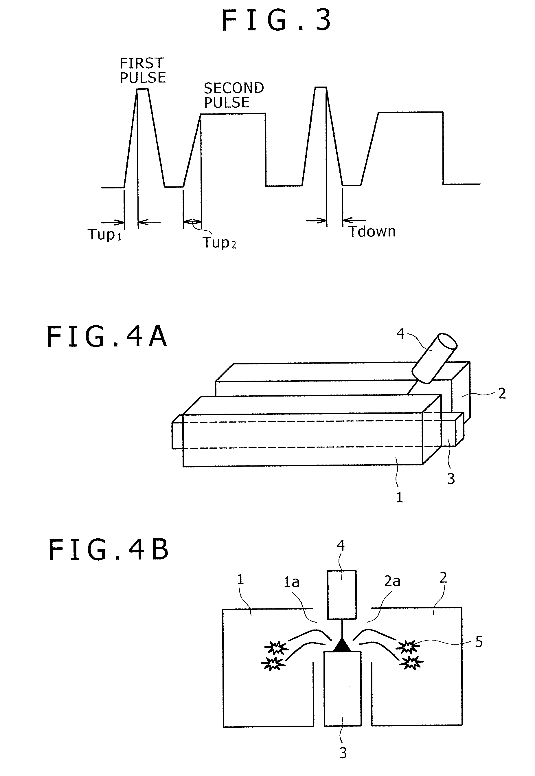
[0080]Hereinafter, examples of the first embodiment of the present invention are explained. Using the welding conditions indicated below and pulse parameter values indicated in Table 1 and Table 2, pulsed arc welding was carried out using carbon dioxide gas as a shield gas to measure a generation rate of spatters. More particularly, spatters were collected by carrying out a welding process inside a copper collector box as shown in FIGS. 4A and 4B. FIG. 4A is its perspective view and FIG. 4B is its schematic cross-sectional view. To carry out the welding process, a welding base metal 3 was sandwiched between the copper collector boxes 1 and 2, and a torch 4 was disposed on the welding base metal 3. Spatters 5 generated from welding were then guided into the collector boxes 1 and 2 through passages 1a and 2a prepared on the upper portion of each of the collector boxes 1 and 2.

[0081]Welding Conditions

[0082]Wire: YGW 11 with a diameter of 1.2 mm of JIS Z3312

[0083]Shield gas: CO2 alone

[0...


PUM

PropertyMeasurementUnit
peak currentaaaaaaaaaa
currentaaaaaaaaaa
currentaaaaaaaaaa

Abstract

Disclosed is a pulsed arc welding method using a pulse current of alternately repeating first and second pulses as a weld current, wherein the first pulse and the second pulse have a pulse waveform of a different pulse peak current level and a different pulse width, respectively, and the following conditions are satisfied: peak current of the first pulse (Ip1)=300 to 700A; peak period (Tp1)=0.3 to 5.0 ms; base current Ib1=30 to 200A, base period (Tb1)=0.3 to 10 ms; peak current of the second pulse (Ip2)=200 to 600A; peak period (Tp2)=1.0 to 15 ms; base current (Ib2)=30 to 200A; and base period (Tb2)=3.0 to 20 ms. In this manner, the consumable electrode arc welding using carbon dioxide gas alone or a mixed gas made mainly of carbon dioxide gas as a shield gas can benefit from stabilized welding arc, improved regularity of droplet transfer, and significantly reduced generation rates of spatters and fumes.

Description

BACKGROUND OF THE INVENTION[0001]1. Field of the Invention[0002]The present invention relates to a pulsed arc welding method using, as a shield gas, carbon dioxide gas alone or a mixed gas containing a carbon dioxide gas as a main component, more particularly, to a pulsed arc welding method in which droplet transfer is realized in synchronism with a group of pulses to thereby stabilize a welding arc and, at the same time, to significantly reduce spatter and fume generation rates.[0003]2. Description of the Related Art[0004]The MAG welding method using, as a shield gas, a mixed gas of Ar and 5 to 30% of CO2 is able to reduce spatter and fume generation rates through the fine droplets, for which the method has been applied to a wide variety of fields in the past. Especially, in the field where high quality welding is required, the pulse MAG welding method wherein one pulse-one droplet transfer is performed by outputting a welding current of about 100 to 350 Hz as a pulse current has n...

Claims


Application Information

Patent Timeline
Patent Type & Authority Applications(United States)
IPC IPC(8): B23K9/09
CPCB23K9/092B23K9/173B23K9/095B23K9/09
Inventor KOSHIISHI, FUSAKISUZUKI, KEIICHIYAMAZAKI, KEIHONMA, MASAHIRO
Owner KOBE STEEL LTD
Why Eureka
Try Eureka