Flat emitter

a flat-emitter and emitter technology, applied in the manufacture of electric discharge tubes/lamps, discharge tube main electrodes, electric discharge systems, etc., can solve the problems of increasing the structure of x-ray tubes, complex work for disposing of emitters, and increasing the strength of x-ray tubes, so as to achieve easy maintenance, increase strength, and high precision

Inactive Publication Date: 2016-12-27
SHIMADZU CORP
View PDF1 Cites 10 Cited by
  • Summary
  • Abstract
  • Description
  • Claims
  • Application Information

AI Technical Summary

Benefits of technology

[0022]According to the flat emitter, the space between the full-lighting current-supply heating leg and the half-lighting current-supply heating leg, which are adjacent to each other, at their terminals can be made larger than the space at their base parts, whereby the distance between the electrode bars for fixing the legs is increased, and electrical insulation between the bars is easily provided. Either one of the sets of the legs is linearly formed, whereby the balance of the flat emitter can easily be kept when the flat emitter is assembled to an electron source. Accordingly, the deformation of the electron emission surface is difficult to occur.
[0026]According to this configuration, the balance of the flat emitter can easily be kept when the flat emitter is assembled to an electron source. Accordingly, the deformation of the electron emission surface is difficult to occur.
[0028]According to this configuration, the flat emitter can easily be assembled to an electron source for an X-ray tube or an electron source for another use with high precision.
[0032]According to this configuration, strength can be increased when the legs are fixed to the base used to assemble the flat emitter to an electron source for an X-ray tube or an electron source for another use. In addition, the legs can be fixed with high precision.
[0033]According to the flat emitter of the present invention, either one of a set of two full-lighting current-supply heating legs for full lighting and a set of two half-lighting current-supply heating legs for half lighting is linearly formed, and the other is bent plural times in zigzag. With this configuration, the space between the full-lighting current-supply heating leg and the half-lighting current-supply heating leg, which are adjacent to each other, at their terminals can be made larger than the space at their base parts. In addition, the balance of the flat emitter can easily be kept, and deformation is difficult to occur.

Problems solved by technology

However, preparing a plurality of emitters according to a purpose makes the structure complicated, and also increases the structure of the X-ray tube.
If the flat emitter including the legs for the current supply and heating has a plate-like shape as illustrated in FIG. 7 or 8, there arise problems such that (1) a complicated mechanism is required to dispose the emitter relative to the electrode, and further, the work for disposing the emitter becomes complicated, and (2) the electron emission region (see the thermoelectrons B in FIG. 9) spreads to the legs upon an irradiation of high current, which fails to form a desired focal spot shape.
However, the structure of the double emitter type 1 has a problem of very small space between the electrode bars ER of the base as apparent from FIG. 13.
Therefore, it is extremely difficult to fix the electrode bars ER to the insulating member such as a ceramic while providing electrical insulation between the electrode bars ER.
However, this is not preferable from the viewpoint of strength.
Therefore, keeping balance is difficult, and the legs are difficult to be fixed to the base with high precision.
(1) The electron emission surface is deformed due to unnatural stress caused by the fixation, which fails to form a desired focal spot shape.
If the double emitter type 2 cannot be disposed with high precision, the focal spot might be enlarged or asymmetry might occur, entailing a problem in which a desired focal spot shape cannot be obtained.

Method used


Image

  • Flat emitter
  • Flat emitter
  • Flat emitter

Examples


Embodiment Construction

[0049]Hereinafter, preferred embodiments of the present invention will be described with reference to the drawings.

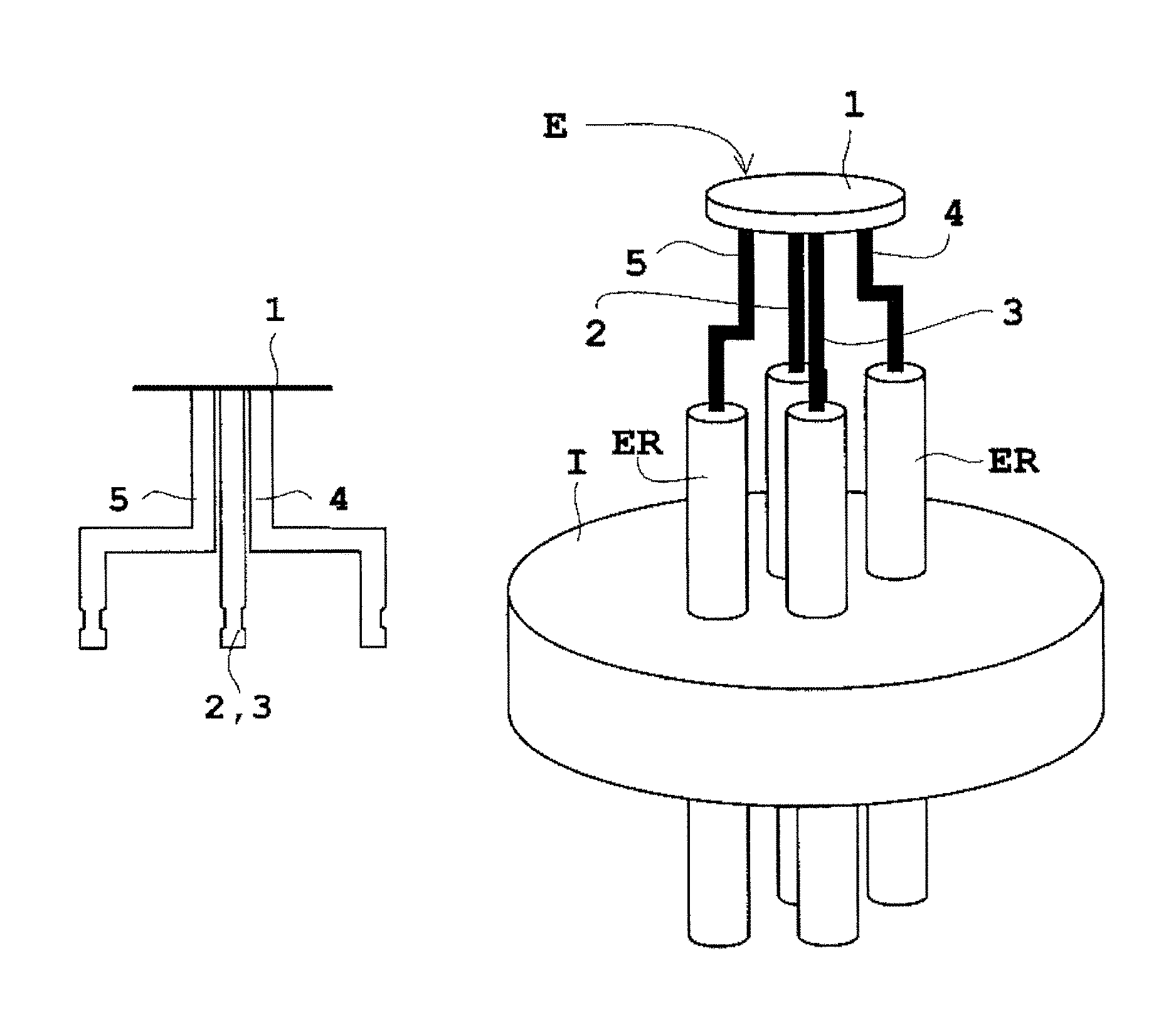
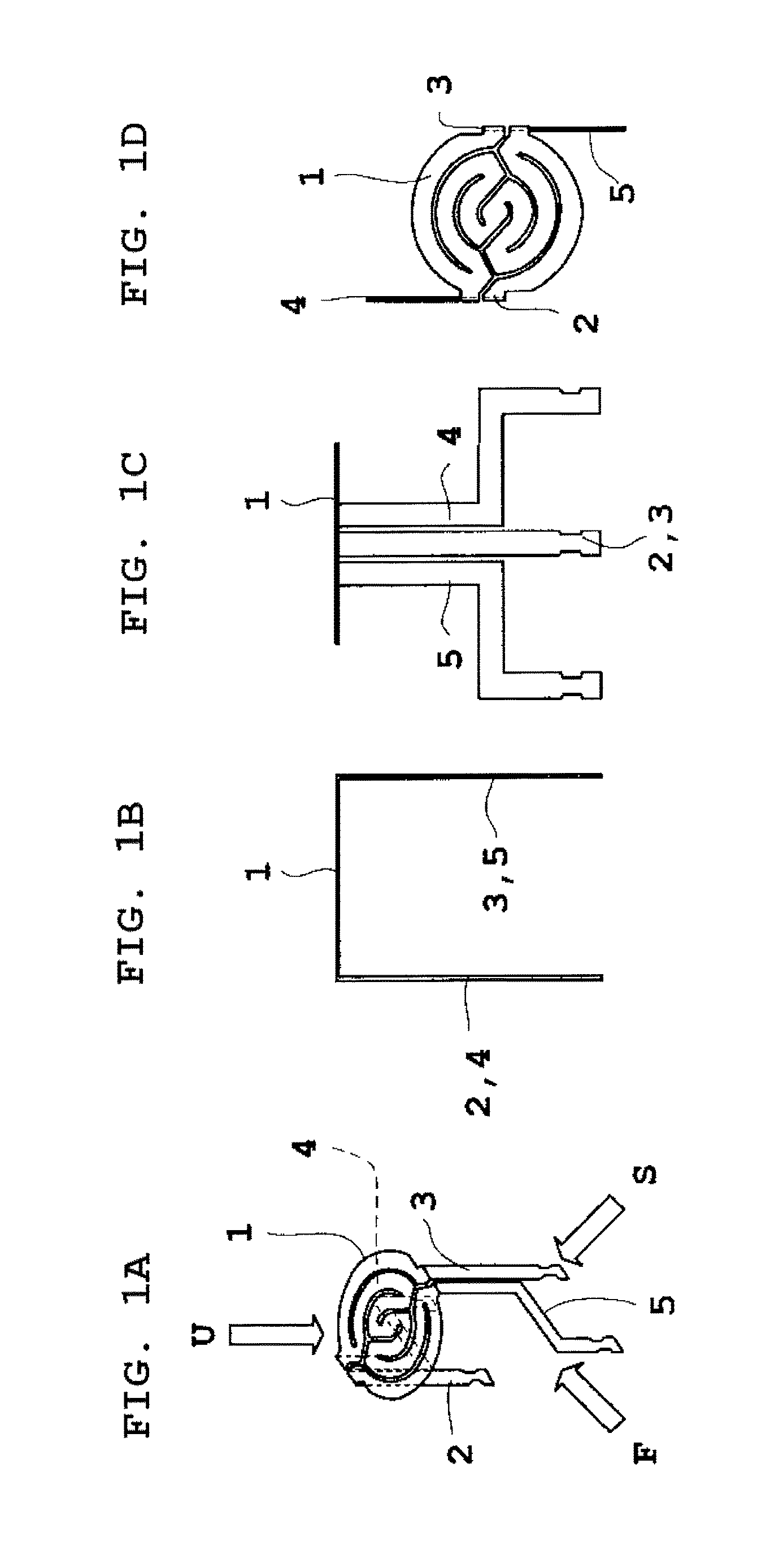
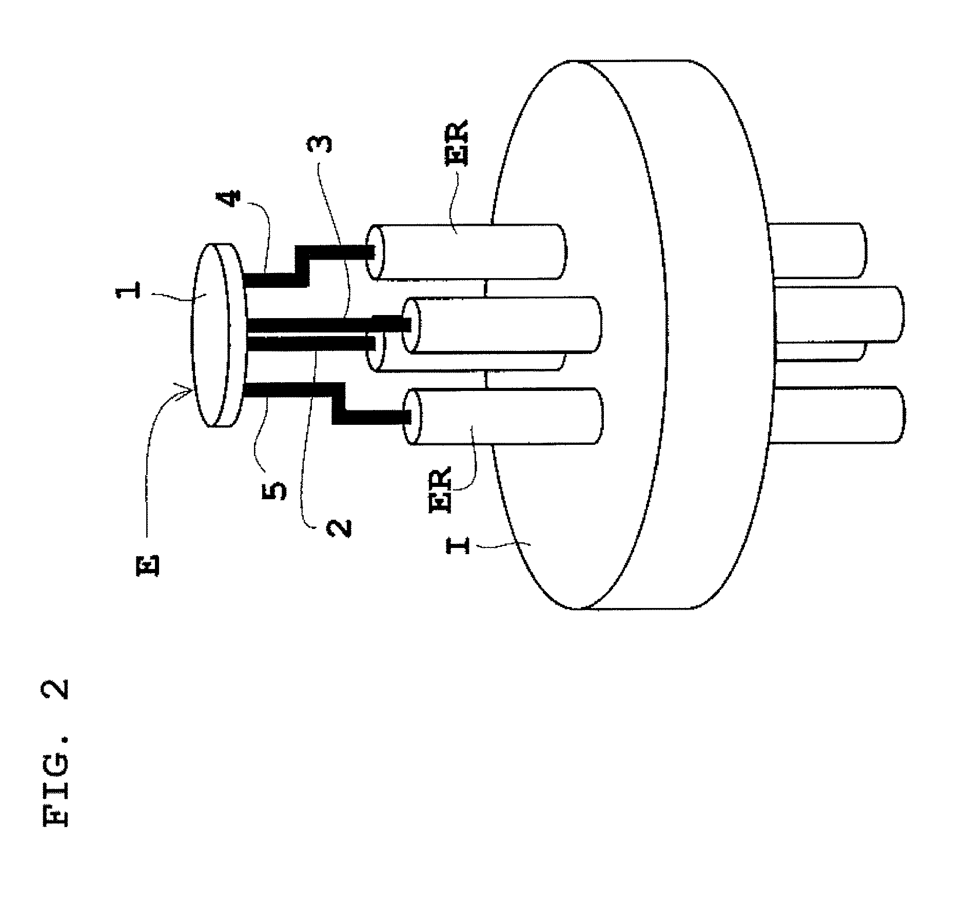
[0050]FIG. 1 is a schematic diagram illustrating a flat double emitter (double emitter type 3) according to an embodiment in which half-lighting current-supply heating legs are bent twice in zigzag, FIG. 2 is a schematic view illustrating that the flat double emitter (double emitter type 3) in FIG. 1 is assembled to a base for an X-ray tube, and FIG. 3 is a diagram schematically illustrating the arrangement relation among an electron emission surface, current-supply heating legs, folding lines, each plane, and a center axis. The present embodiment describes a flat emitter (flat double emitter) configured such that two full-lighting current-supply heating legs are linearly formed and two half-lighting current-supply heating legs are bent twice in zigzag, for example. The flat double emitter configured such that two full-lighting current-supply heating legs are linearly f...


PUM


Abstract

A flat emitter comprises four current-supply heating legs. Half lighting for a small focus in which a current is supplied to heat only a region narrower and full lighting for a large focus in which a current is supplied to heat the entire region are selectable according to the combination of the legs. Either one of a set of the two full-lighting current-supply heating legs for the full lighting and a set of the two half-lighting current-supply heating legs for the half lighting is linearly formed, and the other is formed to be bent plural times in zigzag to set the space between the full-lighting current-supply heating leg and the half-lighting current-supply heating leg, which are adjacent to each other, at their terminals to be larger than the space at their base parts.

Description

BACKGROUND OF THE INVENTION[0001]1. Field of the Invention[0002]The present invention relates to a flat emitter used for an electron source for an X-ray tube or for an electron source for another use, and more particularly to a technique of controlling lighting with four current-supply heating legs.[0003]2. Description of the Related Art[0004]An X-ray apparatus using an X-ray tube reduces a focal size of electrons upon X-raying or photographing a microscopic area, and enlarges a focal size upon X-raying or photographing a subject having a large body thickness in order to reduce a load to an anode. A structure is considered in which a plurality of emitters (also referred to as “filaments”) is prepared and each emitter is switched according to a purpose. However, preparing a plurality of emitters according to a purpose makes the structure complicated, and also increases the structure of the X-ray tube.[0005]In view of this, a single flat emitter that can form a plurality of focal spot...

Claims


Application Information

Patent Timeline
Patent Type & Authority Patents(United States)
IPC IPC(8): H01J9/02H01J1/16H01J35/06
CPCH01J1/16H01J35/06H01J35/064
Inventor KOBAYASHI, TAKUMI
Owner SHIMADZU CORP
Why Eureka
Try Eureka