Coils for horizontal field magnetic resonance imaging

a magnetic resonance imaging and horizontal field technology, applied in the field of magnetic resonance imaging apparatus and procedures, can solve the problems of imposing significant physical constraints on the positioning of patients, claustrophobic environment for patients, and limited antenna configuration and techniques

Inactive Publication Date: 2011-11-08
FONAR
View PDF165 Cites 23 Cited by
  • Summary
  • Abstract
  • Description
  • Claims
  • Application Information

AI Technical Summary

Problems solved by technology

Also, magnetic resonance imaging can obtain images of soft tissues and other features within the body which are not readily visualized using other imaging techniques.
Several factors impose significant physical constraints in the positioning of patients and ancillary equipment in MRI imaging.
Moreover, equipment of this type provides a claustrophobic environment for the patient.
This requirement has further limited available antenna configurations and techniques.
However, these antenna configurations do not provide optimum signal-to-noise ratios in some procedures as, for example, in imaging the spine, head or pelvic region.

Method used


Image

  • Coils for horizontal field magnetic resonance imaging
  • Coils for horizontal field magnetic resonance imaging
  • Coils for horizontal field magnetic resonance imaging

Examples


Embodiment Construction

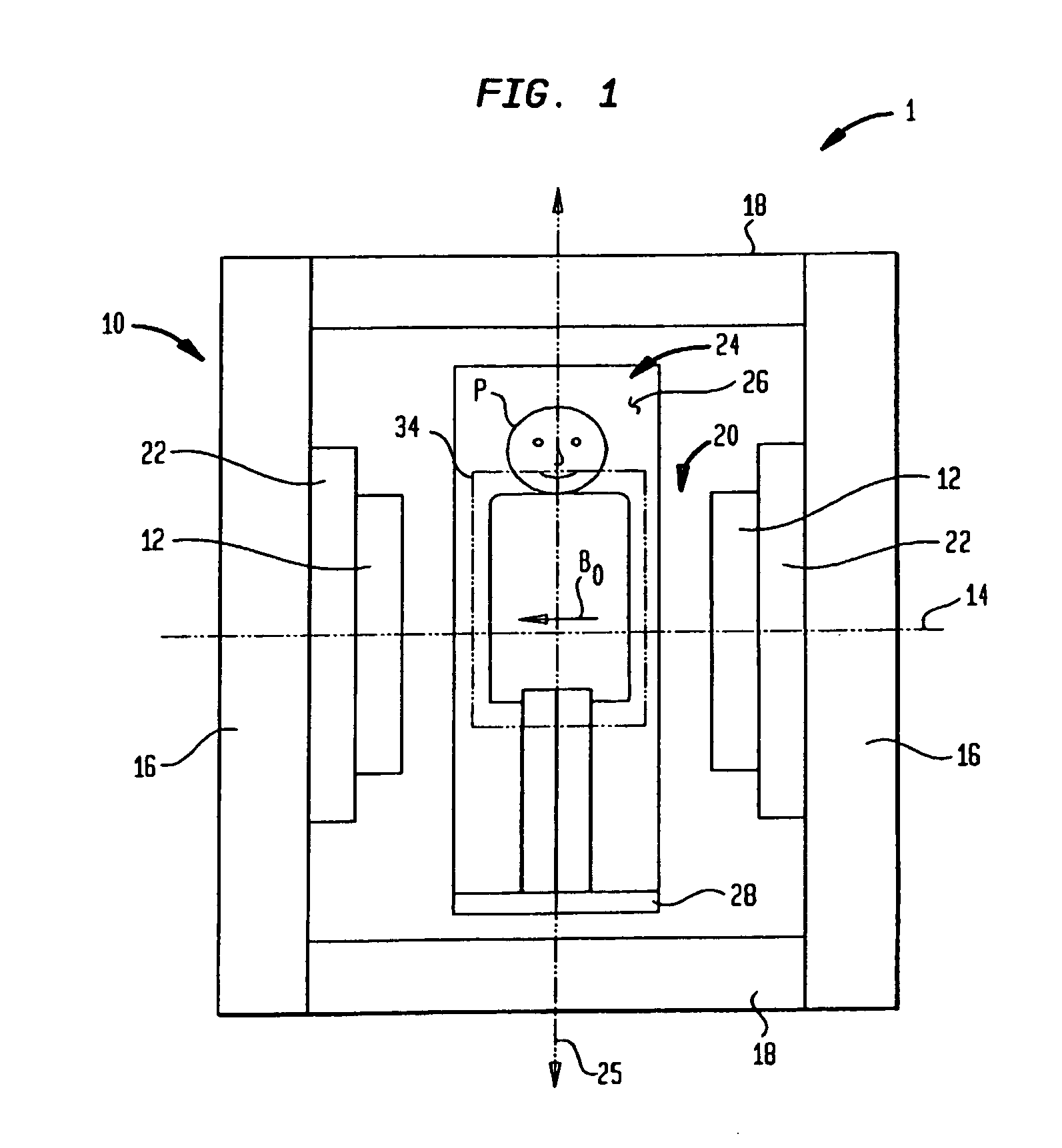
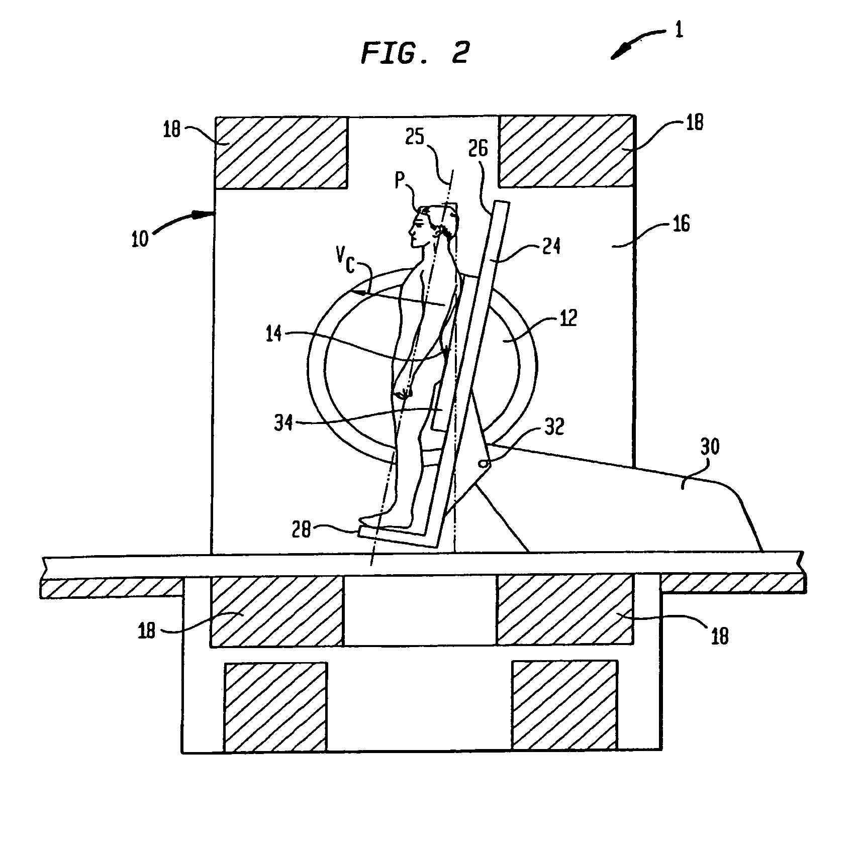
[0026]Turning to FIGS. 1 and 2, there is illustrated an apparatus 1 according to one embodiment of the present invention. The apparatus 1 includes a static field magnet having a frame 10 including a pair of poles 12 spaced apart from one another along a horizontal pole axis 14. Frame 10 further includes flux conducting and return members that, in the particular embodiment illustrated, include a pair of sidewalls 16 and columns 18 extending between the sidewalls16. The particular frame depicted in FIGS. 1 and 2 is generally in accordance with the aforementioned U.S. patent application Ser. No. 09 / 718,946, (hereinafter “the '946 application”) although other configurations can be employed. The opposed poles define a patient-receiving space or gap 20 between them. The magnet further includes a source of magnetic flux adapted to direct into and out of the gap through poles 12 so as to form a static magnetic field having a field vector B0 in the horizontal direction, parallel to pole axis...


PUM


Abstract

Methods and apparatus for performing magnetic resonance imaging are disclosed. In one embodiment coil antennas for use with a horizontal field magnetic resonance imaging apparatus are placed in proximity to the scanning region to obtain magnetic resonance images. In accordance with another aspect of the invention the coil antennas are arranged so as to provide zero mutual inductance between the coils so as to increase the sensitivity of the measurement. Additional embodiments include quadrature coil antennas including two antennas, each having their vector fields substantially perpendicular to each other and to a static magnetic field. Methods for using the disclosed antennas in acquiring magnet resonance scans is also disclosed.

Description

CROSS REFERENCE TO RELATED APPLICATIONS[0001]The present application is a divisional of U.S. application Ser. No. 10 / 266,070, filed on Oct. 7, 2002 and entitled “Coils For Horizontal Field Magnetic Resonance Imaging” claims the benefit of and U.S. Provisional Application No. 60 / 327,329, filed on Oct. 5, 2001 and entitled “Coils For Horizontal Field Magnetic Resonance Imaging,” and U.S. Provisional Application No. 60 / 342,832, filed on Dec. 20, 2001, and entitled “MRI Apparatus Including Planar RF Coil Provided in a Seat,” the disclosures of which are hereby incorporated in their entirety by reference herein.BACKGROUND OF THE INVENTION[0002]The present invention relates to magnetic resonance imaging apparatus and procedures. In magnetic resonance imaging, an object to be imaged as, for example, a body of a human subject, is exposed to a strong, substantially constant static magnetic field. Radio frequency excitation energy is applied to the body, and this energy causes the spin vector...

Claims


Application Information

Patent Timeline
Patent Type & Authority Patents(United States)
IPC IPC(8): A61B5/05
CPCG01R33/307G01R33/341G01R33/3678A61B5/0555G01R33/3806A61B5/055
Inventor DWORKIN, JAYGREEN, CHARLES A.VOTRUBA, JAN
Owner FONAR
Why Eureka
Try Eureka