Supercharge Your Innovation With Domain-Expert AI Agents!

Current sensor assembly

a current sensor and circuit breaker technology, applied in the field of current sensor assembly, can solve the problems of reducing the space available for electronic components, imposing limitations on the size of rigid circuit boards, and limiting the width of residential circuit breakers, so as to reduce the space requirements

Active Publication Date: 2012-02-07
SCHNEIDER ELECTRIC USA INC
View PDF18 Cites 1 Cited by
  • Summary
  • Abstract
  • Description
  • Claims
  • Application Information

AI Technical Summary

Benefits of technology

[0007]In an implementation of the present invention, a current-sensing assembly includes a small-footprint housing and plurality of current transformers all contained within the housing. For example, the assembly can include three current transformers stacked in a pyramid configuration, with two current transformers housed in a bottom portion of the housing and a third current transformer stacked on top of the first two. Current lines can be routed through the bores of the current transformers. Current flowing through the current lines causes induced currents in the current transformers, which can be sensed. The compact nature of the assembly reduces space requirements for the plurality of current transformers on a printed circuit board. This is advantageous, as the areas of printed circuit boards in electronic circuit breakers is generally very limited.
[0008]The current transformers can be mounted in wells in the housing and around elongated rings. The wells and elongated rings maintain the current transformers in fixed positions. The elongated rings are dimensioned just large enough to accommodate insertion of current lines during assembly, but still maintain the current lines in substantially the centers of the bores of the current transformers. Positioning the current lines in substantially the centers of the current transformers increases the accuracy of current measurements. The wells also insulate the current transformers from each other.
[0009]The conducting wires that constitute the coils of the current transformers are accessible through windows in the housing of the current-sensing assembly. The ends of the conducting wires are wrapped around L-shaped pins. The L-shaped pins provide easier access to the pins to allow the wires to be wrapped around the pins during assembly.

Problems solved by technology

One problem associated with this type of rigid circuit board is that the space available for electronic components can be drastically reduced by the space requirements of the connections.
For example, the width of a residential circuit breaker can be limited (e.g., a maximum width of two inches), which imposes limitations on the size of the rigid circuit boards.
Another problem associated with the connections is that they require hand assembly during electronic module assembly.
A current transformer, which includes a coil of wire and a metal core, and must accommodate an insulated conductor routed through it, can require significant space on the rigid circuit board.
Moreover, because a conductor must be routed through the center of the current transformer, and the confines of the rigid circuit board are often tight, wire routing is a concern.

Method used


Image

  • Current sensor assembly
  • Current sensor assembly
  • Current sensor assembly

Examples


Embodiment Construction

[0019]Although the invention will be described in connection with certain preferred embodiments, it will be understood that the invention is not limited to those particular embodiments. On the contrary, the invention is intended to include all alternatives, modifications and equivalent arrangements as may be included within the spirit and scope of the invention as defined by the appended claims.

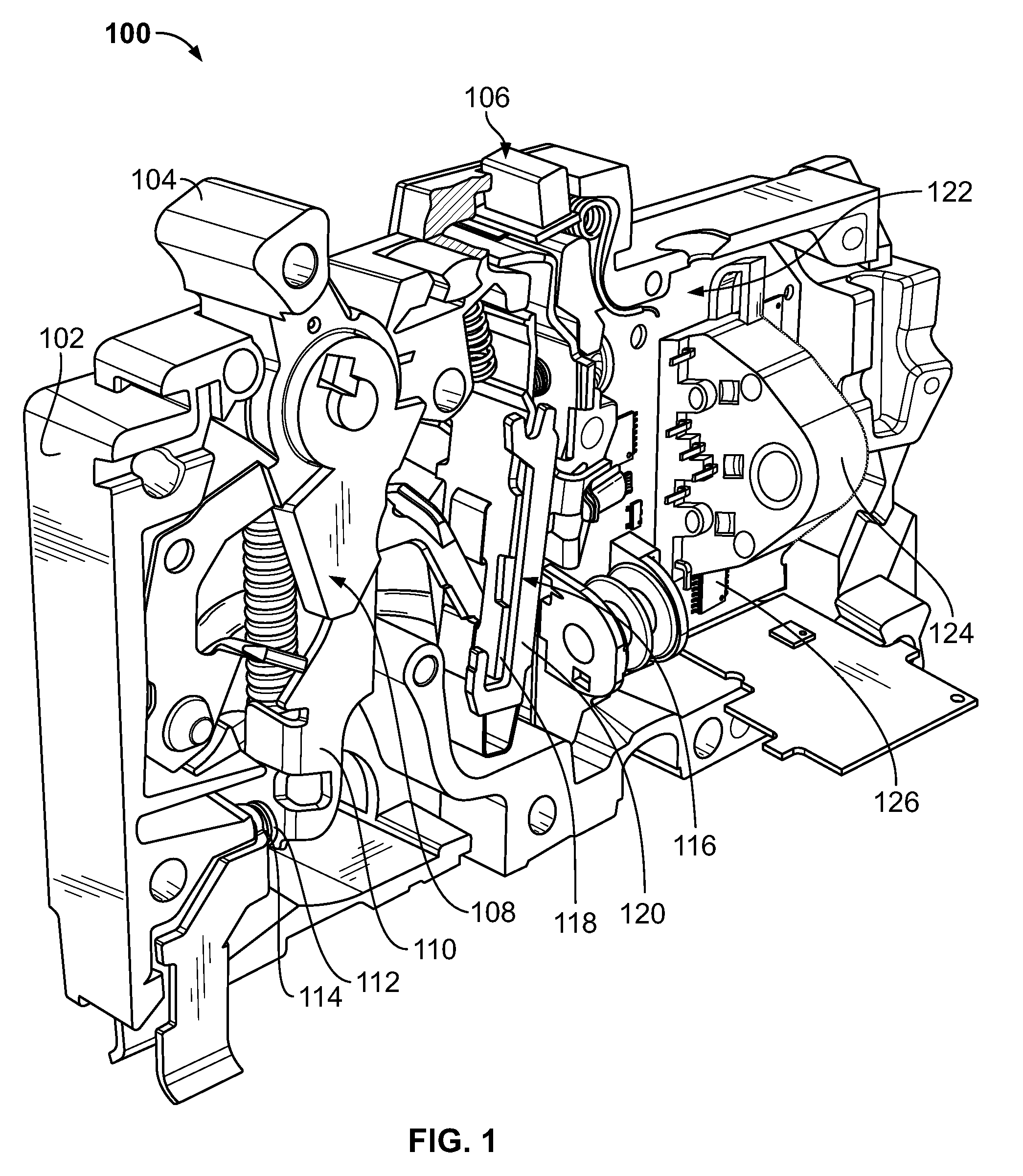
[0020]Referring to FIG. 1, a circuit breaker 100 includes a housing 102, a handle 104, and a test button 106. The housing 102 encloses components of the circuit breaker 100 for one or more pole assemblies. For example, the circuit breaker 100 can be a multi-pole circuit breaker (e.g., a two-pole circuit breaker).

[0021]The handle 104 protrudes through the housing 102 and is generally used for resetting the circuit breaker 100. The handle 104 can also serve as a visual indication of the status of the circuit breaker 100 (e.g., tripped, on, off). The test button 106 is movable between an off pos...


PUM


Abstract

A current-sensing assembly comprising a housing and first and second current transformers contained in and fixed in position by the housing. The assembly includes at least one conducting pin corresponding to each of the first and second current transformers and inserted through the housing to expose a top end and a bottom end. The top end of the pin is electrically coupled to an end of the conducting wire of the corresponding current transformer through a window in the housing coinciding with the current transformer. The top end of a common pin is electrically coupled through the window to the opposite end of the coil conductor. The bottom end of each pin is configured to be coupled to a printed circuit board. The housing includes first and second elongated rings passing substantially through the centers of the current transformers and configured to accept first and second current lines.

Description

[0001]This is a continuation-in-part application of application Ser. No. 12 / 336,058, filed Dec. 16, 2008, which is herein incorporated by reference in its entirety.FIELD OF THE INVENTION[0002]This invention is directed generally to electrical circuit breakers in residential load center applications, and, more particularly, to a current sensors for electrical circuit breakers.BACKGROUND OF THE INVENTION[0003]Circuit breakers are generally used in residential applications to provide circuit protection for low voltage distribution systems. Electrical circuits or electrical systems are protected by the circuit breakers from electrical overcurrent conditions, such as overload conditions as well as low- and high-level short circuit or fault current conditions.[0004]Many current circuit breakers include electronic components that are generally mounted on one or more rigid printed circuit boards (also referred to as rigid circuit boards). The rigid circuit boards have a main surface that pr...

Claims


Application Information

Patent Timeline
Patent Type & Authority Patents(United States)
IPC IPC(8): H02B1/20
CPCH01F27/06H01F38/30H01F2027/065G01R15/185
Inventor POWELL, RODNEYSCHEEL, JERRYGASS, RANDALL J.
Owner SCHNEIDER ELECTRIC USA INC
Features
  • R&D
  • Intellectual Property
  • Life Sciences
  • Materials
  • Tech Scout
  • Unparalleled Data Quality
  • Higher Quality Content
  • 60% Fewer Hallucinations
Learn More