Wide angle display device

a display device and wide angle technology, applied in the field of viewing devices, can solve the problems of large number of lenses, dim image, and inability to insert diffusing screens to provide real images, and achieve the effects of wide surveillance field, thin form factor, and large area

Inactive Publication Date: 2012-05-29
POPOVICH MILAN MOMCILO
View PDF7 Cites 0 Cited by
  • Summary
  • Abstract
  • Description
  • Claims
  • Application Information

AI Technical Summary

Benefits of technology

[0014]It is an object of the present invention to provide an improved door viewer with a wide field of surveillance, a large area viewable image, and a thin form factor requiring only a small door aperture.

Problems solved by technology

Peepholes suffer from the problem that the viewer's face must be pressed against a tiny hole.
The U.S. Pat. No. 4,082,434 apparatus suffers from the problem that the location of the virtual image makes it impractical to insert a diffusing screen to provide a real image.
Further, the small effective diameter of the concave objective lens results in a dim image.
The disadvantage of the U.S. Pat. No. 4,257,670 apparatus is that although the image derived from the plano-convex lens is erect and real, the luminance of the final image suffers from the transmission losses incurred by the large number of lenses.
As in the case of the U.S. Pat. No. 4,082,434 apparatus it is not possible to provide a real image and consequently the user's eye must be positioned close to the eyepiece.
Furthermore, the device is not suitable for typical domestic door applications due to its large overall length.
However, door viewers based on the Ohn invention suffer from the problem that the viewing screen size roughly determines the size of the door hole.
It is therefore difficult to provide a large area screen using a viewer designed according to the principles of the Ohn invention.
There are several problems to be overcome in designing a door viewer with a small door aperture and a large area screen.
This in turn will increase the overall diameter of the lens and hence the size of door hole required.
It is difficult to maximize the photometric and screen thickness requirements simultaneously.
However, the apparatus disclosed by Burstyn is not suitable for numerically small F-number illumination due to the small dimensions of the Fresnel lens facets.

Method used


Image

  • Wide angle display device
  • Wide angle display device
  • Wide angle display device

Examples


first embodiment

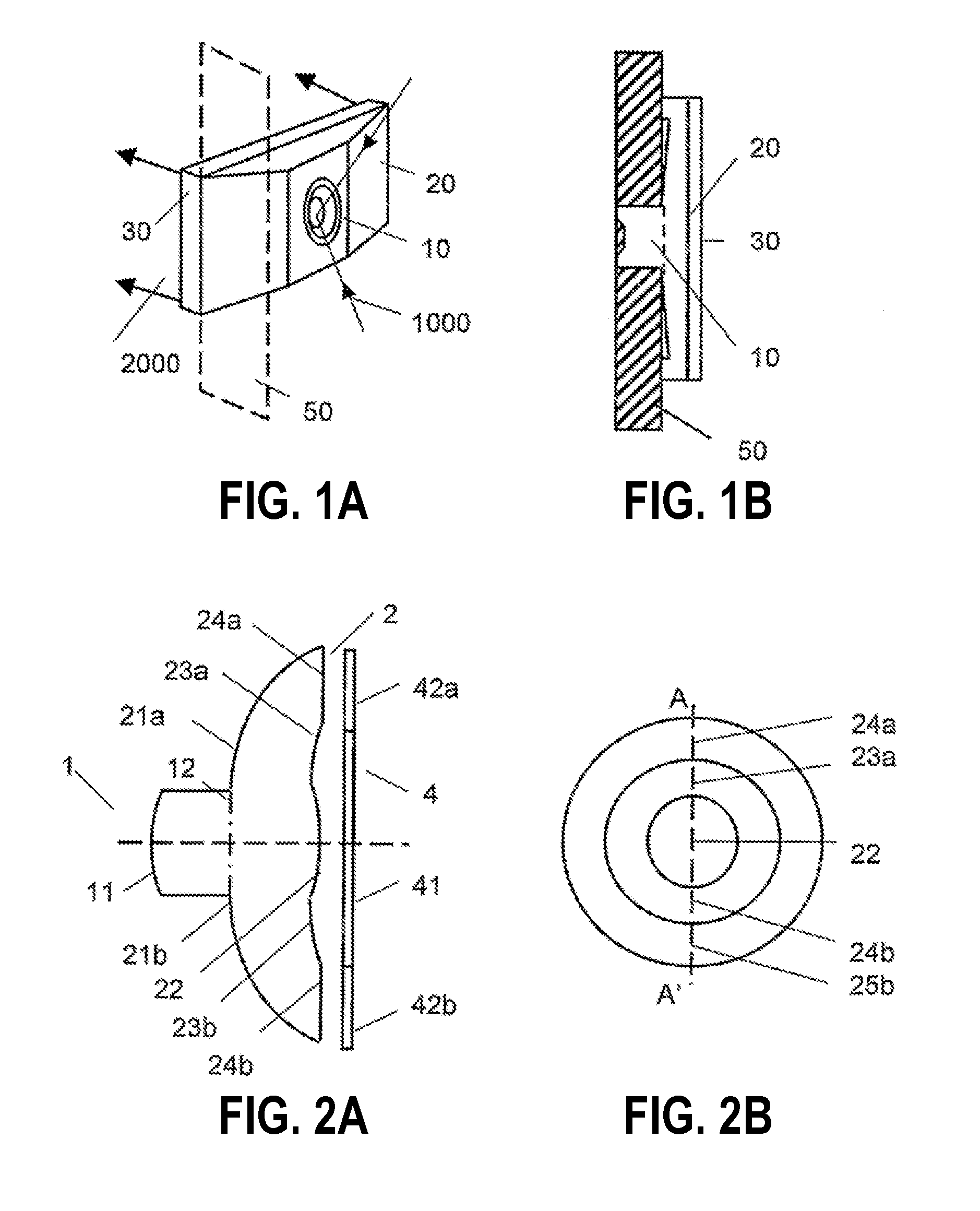
[0077]The basic concept of a door viewer according to the principles of the invention is shown in FIG. 1. FIG. 1A shows a schematic three-dimensional view of a door viewer. In the invention the door viewer comprises a wide-angle lens system 10, multiple reflection lens system 20 and a viewing screen element 30. Said wide-angle lens system comprises at least an image inverter which will be described in more detail below and an optical interface to said multiple reflection lens systems. The wide-angle lens system may further comprise additional lens elements. FIG. 1B shows a schematic side elevation showing the door viewer in a typical operational configuration. The wide-angle lens system is inserted into a cylindrical hole in the door 50. In FIG. 1A the input rays are generally indicated by 1000 and the output rays are generally indicated by 2000. It should be noted that FIG. 1 is provided only for the purposes of showing the approximate appearance of the invention in a typical opera...

second embodiment

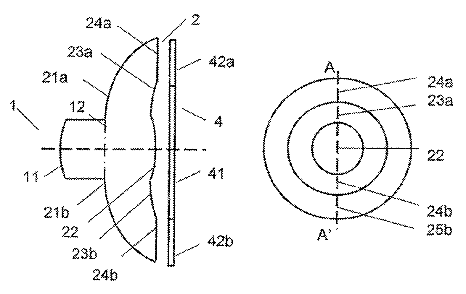
[0097]the proposed wide angle-viewing device is illustrated schematically in FIG. 5. The viewing device comprises the wide-angle lens system 1 and multiple reflection lens system 2 and the diffusing screen 5 and a further lens system 3. Since the characteristics of the wide-angle lens and multiple reflection lens systems are similar to those of the embodiment shown in FIGS. 2-4 the same labels have been used to describe the surface elements. The screen 5 may be based on any of the surface types discussed in relation to the embodiments shown in FIGS. 2-4. The screen comprises a central portion 41 and an outer surrounding portion represented by 41a, 41b. Said inner and outer portions may have substantially different scattering properties.

[0098]FIG. 6 shows the propagation of incident rays in the meridional plane. The rays are defined in a similar fashion to the rays 100,200 of FIG. 4. We consider a low incidence angle ray 110 and a high incidence angle ray 210. The paths of the rays i...


PUM


Abstract

A wide angle viewing apparatus for security applications is disclosed. The apparatus comprises a wide-angle lens and a diffusing screen. The wide-angle lens incorporates an image inverter and a means for eliminating stray light.

Description

REFERENCE TO PRIORITY APPLICATION[0001]The application claims the priority of United Kingdom patent application No. GB0623893.5 filed on 30 Nov. 2006.BACKGROUND OF THE INVENTION[0002]This invention relates to a viewing device, and more particularly to a wide angle viewing apparatus for security applications.[0003]Door viewers for home security are well known. One common approach provides a peephole incorporating a miniature wide-angle lens. Peepholes suffer from the problem that the viewer's face must be pressed against a tiny hole.[0004]U.S. Pat. No. 4,082,434 discloses a wide-angle door viewer comprising a concave objective lens, an intermediate concave lens and a convex eyepiece lens. The eyepiece lens is positioned at a predetermined distance from the objective lens. The intermediate lens corrects the aberration of the erect virtual image formed by the objective lens. The eyepiece lens magnifies the image formed by the intermediate lens. A magnified final erect virtual image is ...

Claims


Application Information

Patent Timeline
Patent Type & Authority Patents(United States)
IPC IPC(8): G02B27/32
CPCG02B17/0808G02B25/04G02B17/04G02B17/08
Inventor POPOVICH, MILAN MOMCILOMESSIOU, ANTOINE YVON
Owner POPOVICH MILAN MOMCILO
Why Eureka
Try Eureka