Electrical connecting structure for piezoelectric element, piezoelectric actuator, head suspension, and electrical connecting structure for conductive part

a piezoelectric actuator and electric connection technology, applied in the direction of head support, record information storage, instruments, etc., can solve the problems of deteriorating the reliability of electric connection to the piezoelectric element, insufficient bonding strength, and difficulty in carrying out the wire bonding process on the piezoelectric elemen

Active Publication Date: 2012-06-12
NHK SPRING CO LTD
View PDF10 Cites 26 Cited by
  • Summary
  • Abstract
  • Description
  • Claims
  • Application Information

AI Technical Summary

Benefits of technology

[0012]An object of the present invention is to provide an electrical connecting structure for a piezoelectric element, capable of providing the piezoelectric element with electrical connection without deteriorating the productivity and reliability of the piezoelectric element. Also provided by the present invention are a piezoelectric actuator employing the piezoelectric element, a head suspension employing the piezoelectric actuator, and an electrical connecting structure for a conductive part.
[0015]This aspect correctly accomplishes wiring to the piezoelectric element without damaging the piezoelectric element or deteriorating the reliability thereof.

Problems solved by technology

An important issue for the head suspension employing the dual actuator system is how to supply electricity to the piezoelectric elements.
This related art has a risk of cracking the piezoelectric element because the wire bonding process applies a local stress on the piezoelectric element to secure a bonding strength.
If the wire bonding process is carried out with a reduced force not to crack the piezoelectric element, the bonding strength will be insufficient to deteriorate the reliability of electric connection to the piezoelectric element.
It is very difficult to carry out the wire bonding process on piezoelectric elements to satisfy both the productivity and reliability of the piezoelectric elements.

Method used


Image

  • Electrical connecting structure for piezoelectric element, piezoelectric actuator, head suspension, and electrical connecting structure for conductive part
  • Electrical connecting structure for piezoelectric element, piezoelectric actuator, head suspension, and electrical connecting structure for conductive part
  • Electrical connecting structure for piezoelectric element, piezoelectric actuator, head suspension, and electrical connecting structure for conductive part

Examples


Embodiment Construction

[0031]Electrical connecting structures for piezoelectric elements, piezoelectric actuators, head suspensions, and electrical connecting structures for conductive parts according to embodiments of the present invention will be explained with reference to the drawings.

[0032]First, a head suspension according to an embodiment of the present invention will be explained.

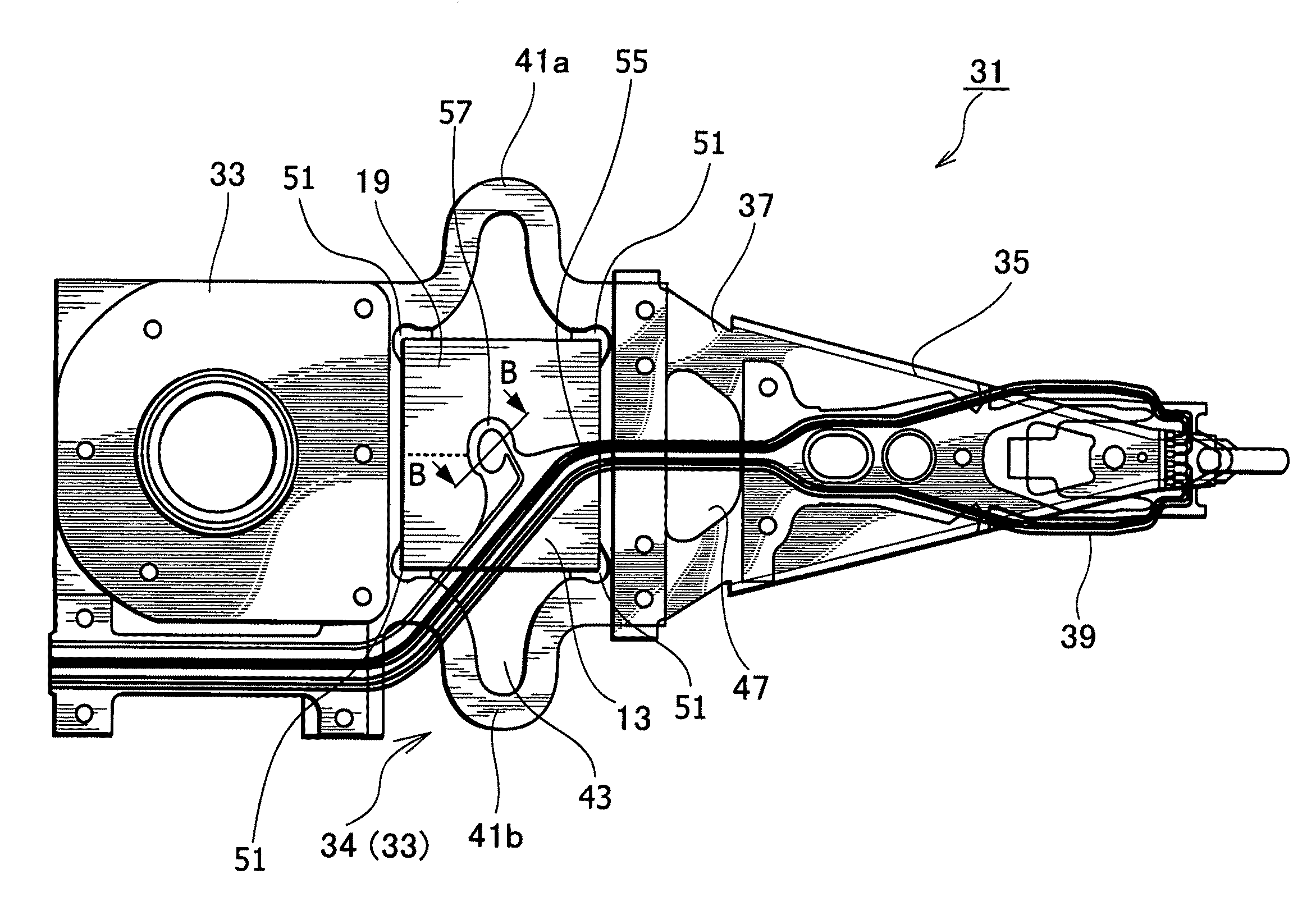
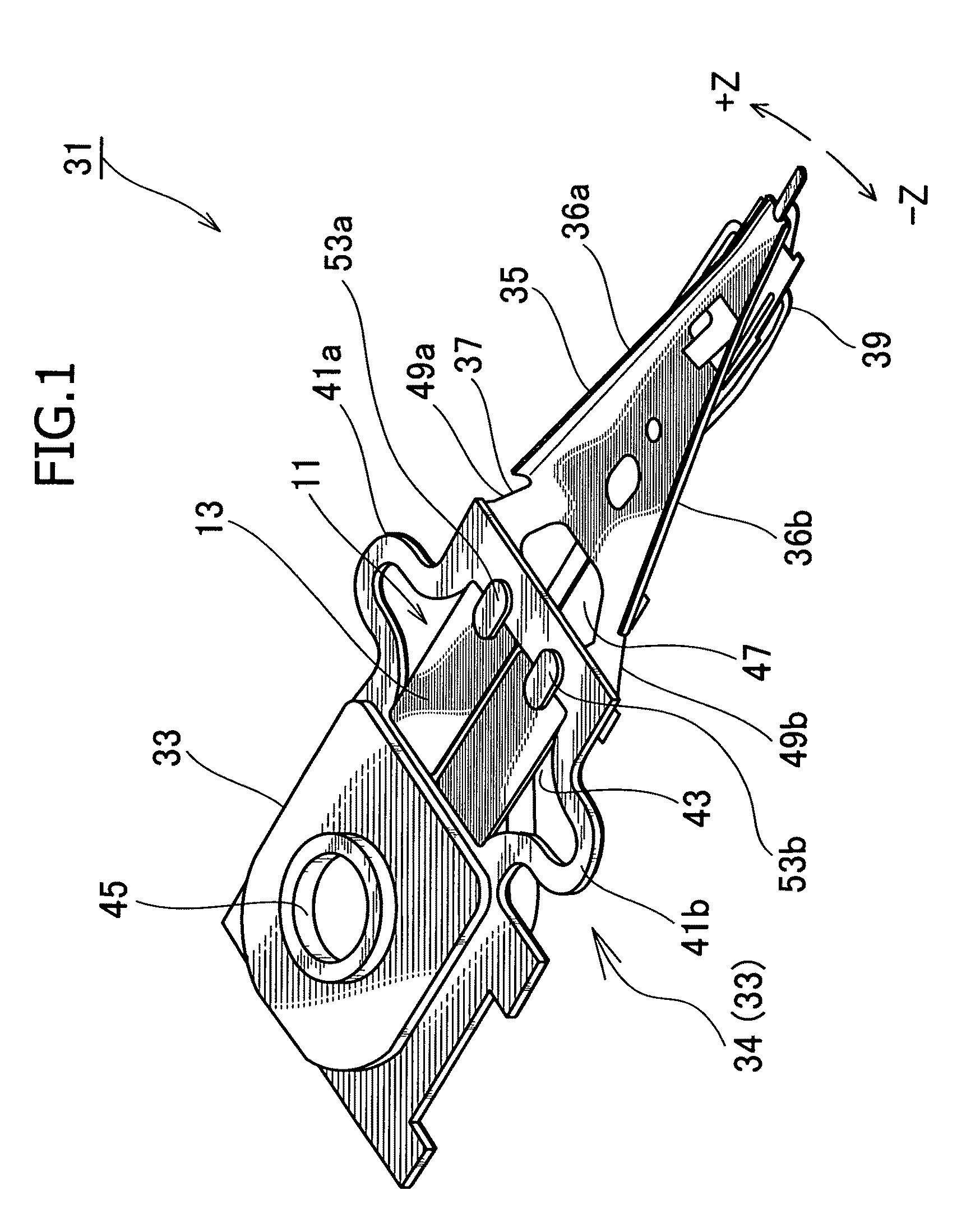
[0033]FIG. 1 is a perspective view illustrating a head suspension according to an embodiment of the present invention.

[0034]The head suspension 31 includes a base plate 33 to which a piezoelectric actuator 11 consisting of a piezoelectric element 13 is attached, a load beam 35, a connection plate 37 functioning as a hinge, and the like. The base plate 33 has an opening 43 in which the piezoelectric element 13 is arranged. The piezoelectric element 13 deforms in response to an applied voltage, to move a front end of the load beam 35 in a sway direction, i.e., a widthwise direction of the head suspension 31.

[0035]The base p...


PUM

PropertyMeasurementUnit
thicknessaaaaaaaaaa
thicknessaaaaaaaaaa
thicknessaaaaaaaaaa

Abstract

A piezoelectric element 13 has a common electrode 19 that receives electricity from a terminal 57. The terminal 57 has a through hole 67 and an electric insulating layer 61. The piezoelectric element 13 is arranged so that the common electrode 19 faces the electric insulating layer 61 of the terminal 57. A liquid stopper 69 is formed around the through hole 67 so as to come between the common electrode 19 and the terminal 57 when the common electrode 19 and terminal 57 are set to face each other. A liquid conductive adhesive 71 is injected into the through hole 67 to fill a gap defined by the liquid stopper 69 between the terminal 57 and the common electrode 19 and secure electric connection between the terminal 57 and the common electrode 19. This configuration improves the reliability of wiring to the piezoelectric element and prevents the piezoelectric element from being damaged.

Description

BACKGROUND OF THE INVENTION[0001]1. Field of the Invention[0002]The present invention relates to a head suspension for supporting a magnetic head slider in a magnetic disk drive. In particular, the present invention relates to a piezoelectric actuator having a piezoelectric element that deforms in response to an applied voltage, to minutely move the magnetic head slider in a widthwise direction of the head suspension.[0003]2. Description of Related Art[0004]Small-sized, precision information devices are rapidly advancing and needs for micro-actuators capable of conducting positioning control for very small distances are increasing. Such micro-actuators are highly needed by, for example, optical systems for correcting focuses and inclination angles, ink jet printers for controlling ink heads, and magnetic disk drives for controlling magnetic heads.[0005]The magnetic disk drives have an urgent issue to solve, i.e., increasing storage capacity. The storage capacity of a magnetic disk d...

Claims


Application Information

Patent Timeline
Patent Type & Authority Patents(United States)
IPC IPC(8): G11B21/10
CPCG11B5/4846G11B5/486H01L41/0986H01L41/0475G11B5/5552G11B5/4873H10N30/875H10N30/206
Inventor OKAWARA, OSAMUANDO, TOSHIKIMORIYA, NAOKI
Owner NHK SPRING CO LTD
Why Eureka
Try Eureka