Electrical connecting structure and electrical connecting method for piezoelectric element, piezoelectric actuator, and head suspension

a piezoelectric actuator and electric connection technology, applied in the direction of generator/motor, record information storage, instruments, etc., can solve the problems of insufficient bonding strength to deteriorate the reliability of electric connection to the piezoelectric element, insufficient clearance with respect to a magnetic disk, and related art has a risk of cracking the piezoelectric elemen

Active Publication Date: 2010-07-01
NHK SPRING CO LTD
View PDF2 Cites 50 Cited by
  • Summary
  • Abstract
  • Description
  • Claims
  • Application Information

AI Technical Summary

Benefits of technology

[0028]According to the third and fourth aspects of the present invention, the piezoelectric actuator and head suspension provide the effect of the first aspect.

Problems solved by technology

An important issue for the head suspension employing the dual actuator system is how to supply electricity to the piezoelectric elements.
This related art has a risk of cracking the piezoelectric element because the wire bonding process applies a local stress on the piezoelectric element to secure a bonding strength.
If the wire bonding process is carried out with a reduced force not to crack the piezoelectric element, the bonding strength will be insufficient to deteriorate the reliability of electric connection to the piezoelectric element.
The wire bonding or the conductive paste, however, causes a swell protruding from an end face of the piezoelectric element or an inclination of the terminal part, to make a clearance with respect to a magnetic disk insufficient.
In this way, it is very difficult to carry out wiring to the piezoelectric elements without damaging the piezoelectric elements or deteriorating the reliability thereof.

Method used


Image

  • Electrical connecting structure and electrical connecting method for piezoelectric element, piezoelectric actuator, and head suspension
  • Electrical connecting structure and electrical connecting method for piezoelectric element, piezoelectric actuator, and head suspension
  • Electrical connecting structure and electrical connecting method for piezoelectric element, piezoelectric actuator, and head suspension

Examples


Embodiment Construction

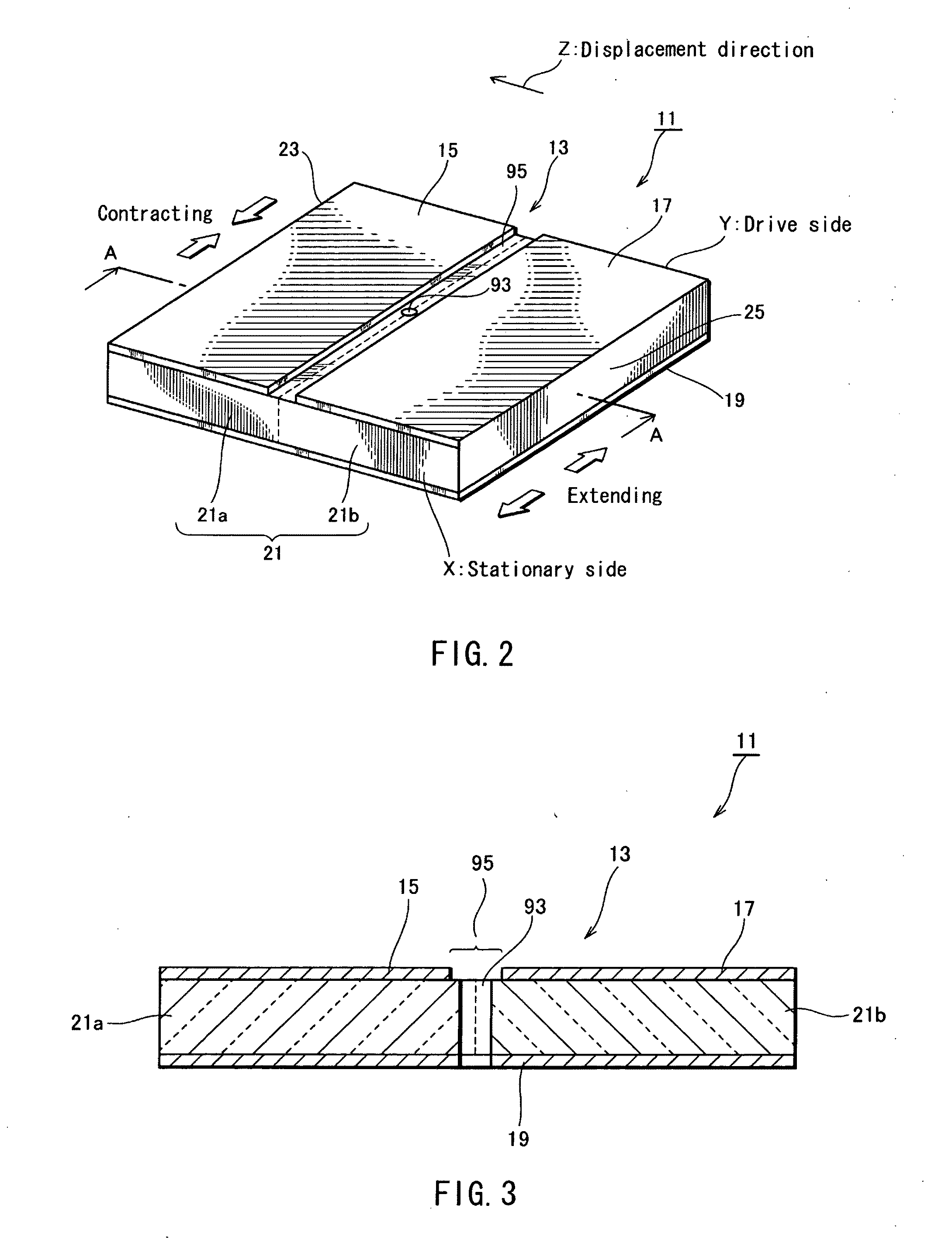
[0045]An electrical connecting structure for a piezoelectric element according to the present invention achieves wiring to the piezoelectric element without deteriorating the productivity and reliability of the piezoelectric element. For this, the electrical connecting structure includes a through hole formed through the piezoelectric element from an electrode on a first end face of the piezoelectric element to a second end face of the piezoelectric element that is opposite to the first end face. A liquid conductive adhesive is injected into the through hole to join the electrode of the piezoelectric element with a terminal used to apply a voltage to the electrode.

[0046]Electrical connecting structures, electrical connecting methods, piezoelectric actuators, and head suspensions according to embodiments of the present invention will be explained in detail with reference to the drawings.

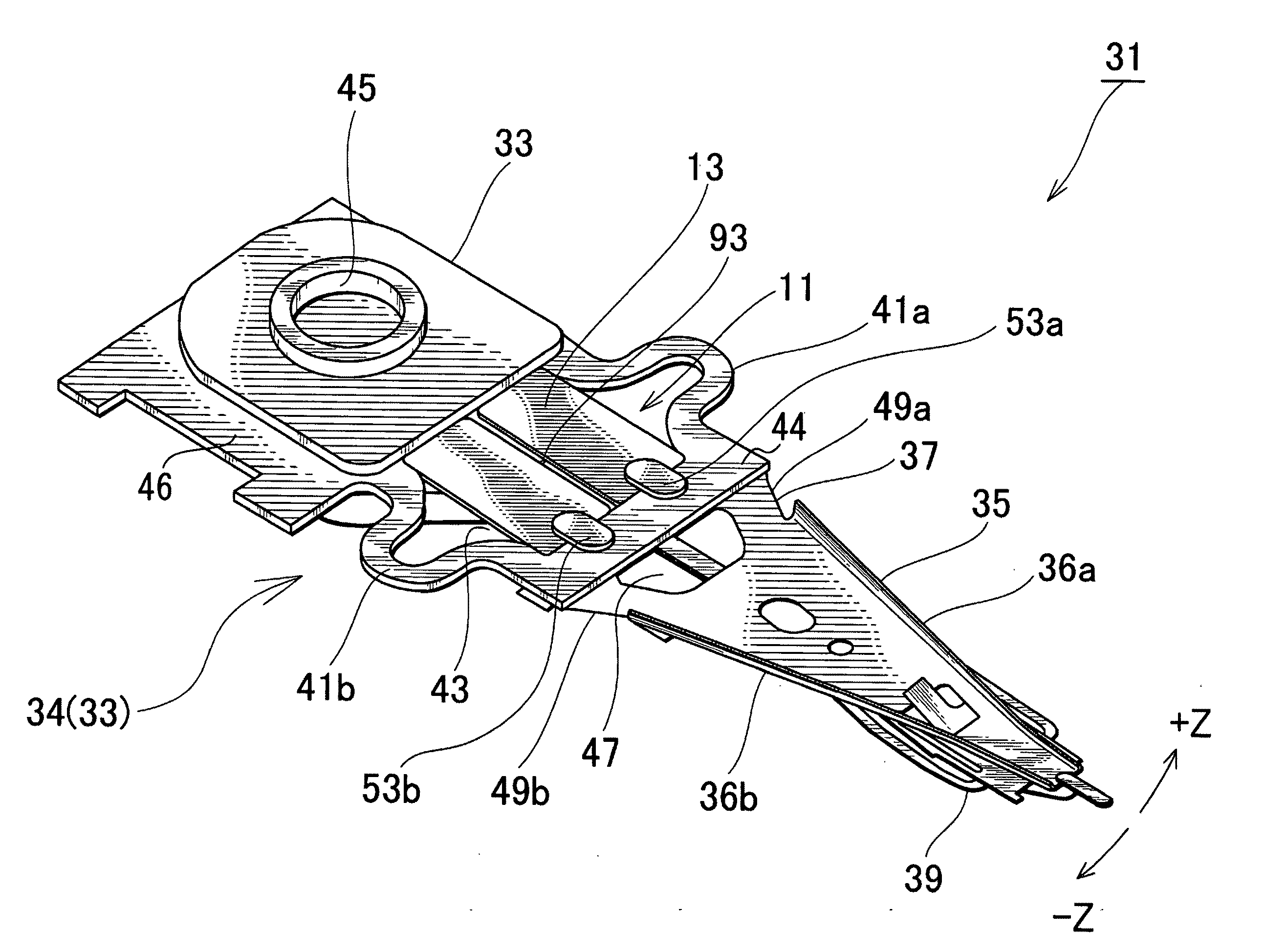
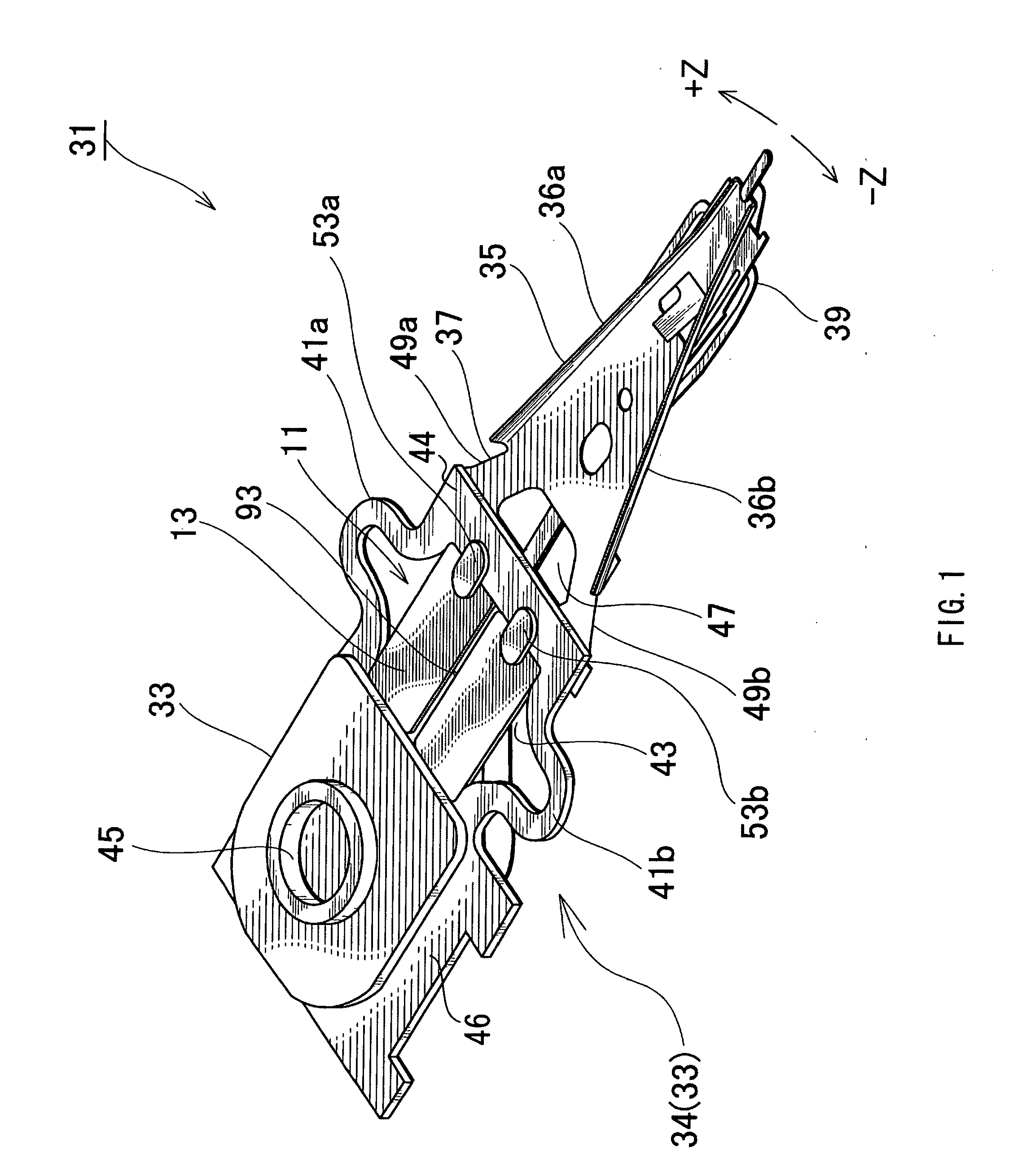
[0047]First, a head suspension as an object according to an embodiment of the present invention wi...


PUM

PropertyMeasurementUnit
thicknessaaaaaaaaaa
thicknessaaaaaaaaaa
thicknessaaaaaaaaaa

Abstract

An electrical connecting structure for a piezoelectric element enables wiring to the piezoelectric element to be carried out without deteriorating the productivity and reliability of the piezoelectric element. The electrical connecting structure is formed by facing a common electrode of the piezoelectric element to a terminal that supplies power to the common electrode and by injecting a conductive adhesive into a through hole, which is formed substantially at the center of the piezoelectric element, from an opening of the through hole that is on the opposite side of the common electrode, thereby securing electrical connection between the terminal and the common electrode of the piezoelectric element.

Description

BACKGROUND OF THE INVENTION[0001]1. Field of the Invention[0002]The present invention relates to an electrical connecting structure and electrical connecting method for a piezoelectric element that deforms in response to a voltage applied thereto, a piezoelectric actuator that incorporates the piezoelectric element to drive an objective part according to deformation of the piezoelectric element, and a head suspension provided with the piezoelectric actuator. In particular, the present invention relates to an electrical connecting structure and electrical connecting method for a piezoelectric element, capable of conducting wiring work for the piezoelectric element in such a way as to prevent the piezoelectric element from being damaged and secure the reliability of the piezoelectric element, a piezoelectric actuator employing such a piezoelectric element, and a head suspension employing such a piezoelectric actuator.[0003]2. Description of Related Art[0004]Small-sized, precision info...

Claims


Application Information

Patent Timeline
Patent Type & Authority Applications(United States)
IPC IPC(8): G11B21/24H01L41/053
CPCG11B5/486G11B5/4873H05K3/321H05K3/361H05K2201/096H05K2201/10083H05K2201/10666H01L41/0475H10N30/875
Inventor FUCHINO, HIDEKI
Owner NHK SPRING CO LTD
Why Eureka
Try Eureka