Radio base station receiver and program

a radio base station and receiver technology, applied in the field of radio base station receivers, can solve the problems of increasing the number of users, and increasing the cost of base station infrastructure, so as to reduce the number of resources, reduce the scale of the circuit, and increase the number of users.

Inactive Publication Date: 2012-08-14
FUJITSU LTD
View PDF14 Cites 0 Cited by
  • Summary
  • Abstract
  • Description
  • Claims
  • Application Information

AI Technical Summary

Benefits of technology

[0020]According to the present invention, it is possible to reduce the number of resources required by the channel decoding process unit because the process method of the channel decoding process unit is controlled according to services. Accordingly, it is possible to reduce the scale of a circuit in the radio base station receiver. It is also possible to easily increase the number of users even when there are not so many resources for the channel decoding processes.
[0021]Therefore, according to the present invention, the resources for the channel decoding processes are used in common such that circuit efficiency is improved, and the channel decoding process unit can be used efficiently.

Problems solved by technology

Additionally, competition among network operators has become more intensive, and the infrastructures of the base stations and the like are increasingly required to be of a lower cost.
Accordingly, a problem is created in which the circuit scale of the radio base station receiver becomes large.

Method used


Image

  • Radio base station receiver and program
  • Radio base station receiver and program
  • Radio base station receiver and program

Examples


embodiment 1

[0035]First, embodiment 1 of the present invention is explained by referring to FIGS. 4 through 7. It is to be noted that expressions such as “allocate a resource for a despreading process to a despreading process unit 3” and the like used hereinbelow have the meaning “allocate a resource for a despreading process used for executing a despreading process on a received signal on which the despreading process should be executed in a despreading process unit”.

[0036]FIG. 4 is a function block diagram of embodiment 1 of the present invention. The configuration of FIG. 4 is different from the conventional example of FIG. 2 in that a resource allocation control unit 2 is provided between the despreading process unit 3 and a channel decoding process unit 4, and that the maximum number M of resources for the channel decoding processes allocated to the channel decoding process unit 4 is smaller than the maximum number N of resources for the despreading processes allocated to the despreading p...

embodiment 2

[0053]Next, embodiment 2 of the present invention is explained, by referring to FIGS. 8 through 10.

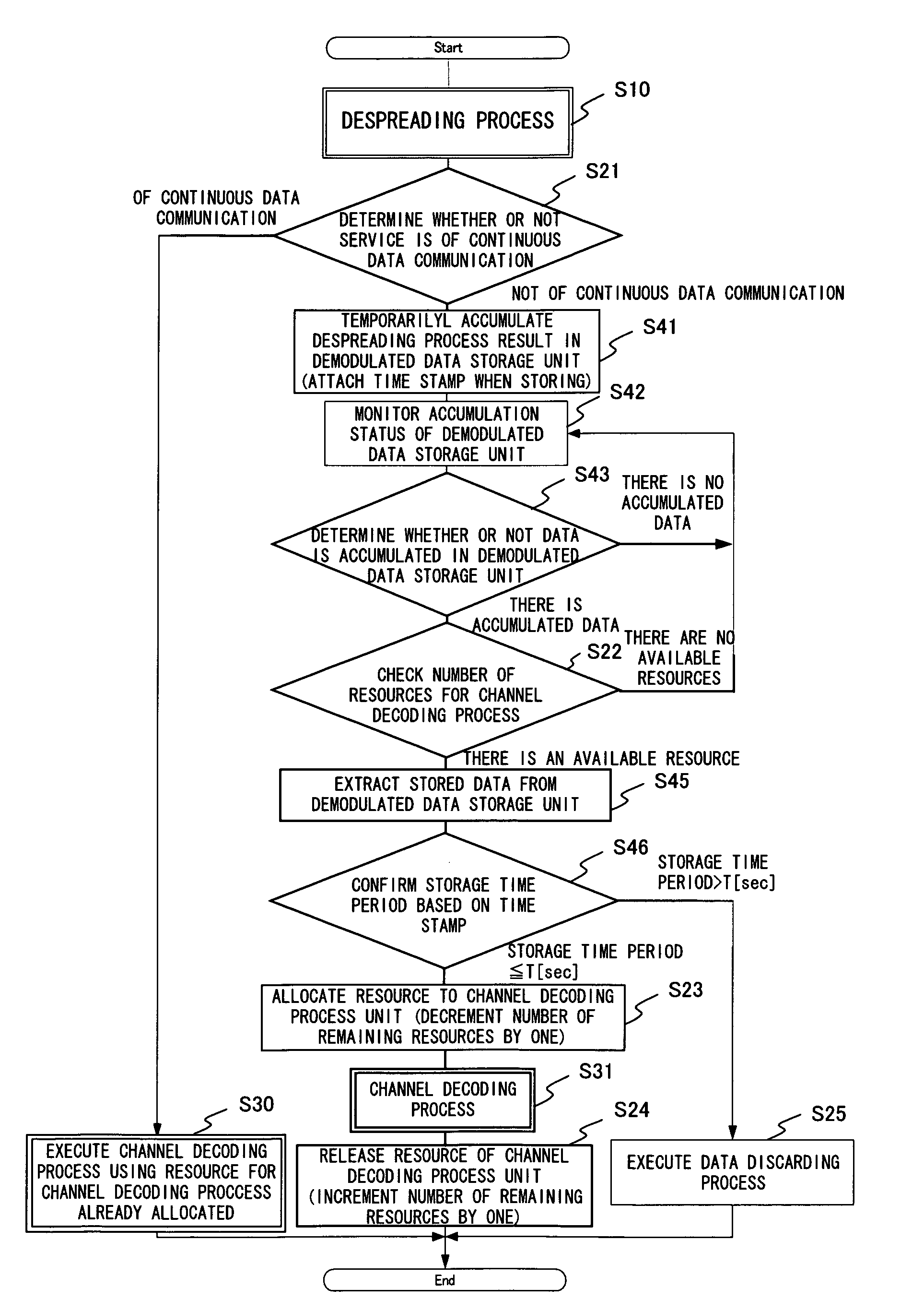
[0054]FIG. 8 is a function block diagram of embodiment 2 of the present invention. The function block diagram in FIG. 8 is different from that of embodiment 1 shown in FIG. 4 in that the function block diagram in FIG. 8 includes a demodulated data storage unit 5. In embodiment 2, by including the demodulated data storage unit 5, it is possible to wait until the resource for the channel decoding process becomes available while holding in the demodulated data storage unit 5 the demodulated signal as the despreading process result even when the resources for the channel decoding processes are depleted temporarily.

[0055]Accordingly, it is possible to process data when the resource for the channel decoding process becomes available in embodiment 2, while in embodiment 1, the demodulated signals have to be discarded when there is no available resource for the channel decoding process.

[0056]I...


PUM


Abstract

A resource allocation control unit is provided between the despreading process unit and the channel decoding process unit of a radio base station receiver, and a resource for a channel decoding process is allocated only when there is actually user communication data in a communication service that is not of a continuous data communication under control of the resource allocation control unit. Thereby, the number of resources of the channel decoding process unit is smaller than the number of resources for despreading processes corresponding to the number of users that can receive the services simultaneously.

Description

BACKGROUND OF THE INVENTION[0001]1. Field of the Invention[0002]The present invention relates to a radio base station receiver that conducts reception of communication data from a plurality of users, and particularly to a method of managing process resources for processing received data of an uplink transmission (data transmitted from mobile terminals to the radio base station) in the radio base station receiver.[0003]2. Description of the Related Art[0004]Recently, a 3rd generation service started in mobile radio systems, and a CDMA (Code Division Multiple Access) method is used in the mobile radio systems of the 3rd generation. The mobile radio system of the CDMA method such as the above is disclosed in Patent Document 1 below.[0005]FIG. 1 shows an example of a basic configuration of a radio base station receiver in a mobile radio system using the CDMA method. In the receiver shown in FIG. 1, received data of an uplink transmission is converted from data in a radio frequency band ...

Claims


Application Information

Patent Timeline
Patent Type & Authority Patents(United States)
IPC IPC(8): H04W72/00H04B1/707H04J13/00H04W76/02H04W88/00H04W88/08H04W88/14
CPCH04W88/08
Inventor HAMADA, SEIJI
Owner FUJITSU LTD
Why Eureka
Try Eureka