Connector housing with integrated cable clamp

a technology of connecting cable and cable clamp, which is applied in the direction of connection, electrical apparatus, coupling device connection, etc., can solve the problems of cable damage, cable is unavoidable, cable clamping can only absorb low, etc., and achieve the effect of counteracting high tensile load

Active Publication Date: 2012-08-21
HARTING ELECTRIC GMBH & CO KG
View PDF11 Cites 16 Cited by
  • Summary
  • Abstract
  • Description
  • Claims
  • Application Information

AI Technical Summary

Benefits of technology

[0009]The invention therefore is based on the objective of disclosing a device for clamping a cable on a connector that is able to accommodate cables with a broad variety of diameters, counteracts high tensile loads acting upon the cable and prevents the cable from turning.
[0018]In one practical embodiment, the outer surface of the pressure screw is recessed or shaped such that the grip on the screw is improved or a tool can be attached.
[0020]In another practical embodiment, the inner ends of the clamping elements on the mating side are provided with additional means that allow a superior adhesion of the clamping elements on the cable.

Problems solved by technology

It is disadvantageous that the cable clamps of known clamping systems can only absorb low tensile loads because the clamping arms point in the direction of the tensile load and therefore cannot exert significant clamping forces upon the cable.
In the latter variation, it is disadvantageous that turning of the crown spring and therefore the cable is unavoidable when the strain relief device is screwed down such that the conductors of the cable may become damaged.

Method used


Image

  • Connector housing with integrated cable clamp
  • Connector housing with integrated cable clamp
  • Connector housing with integrated cable clamp

Examples


Embodiment Construction

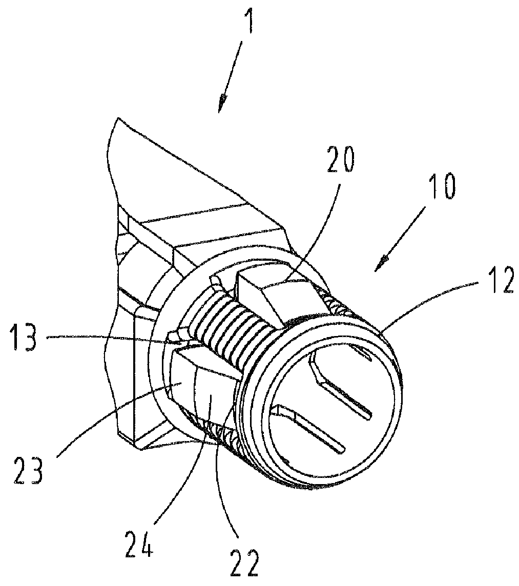
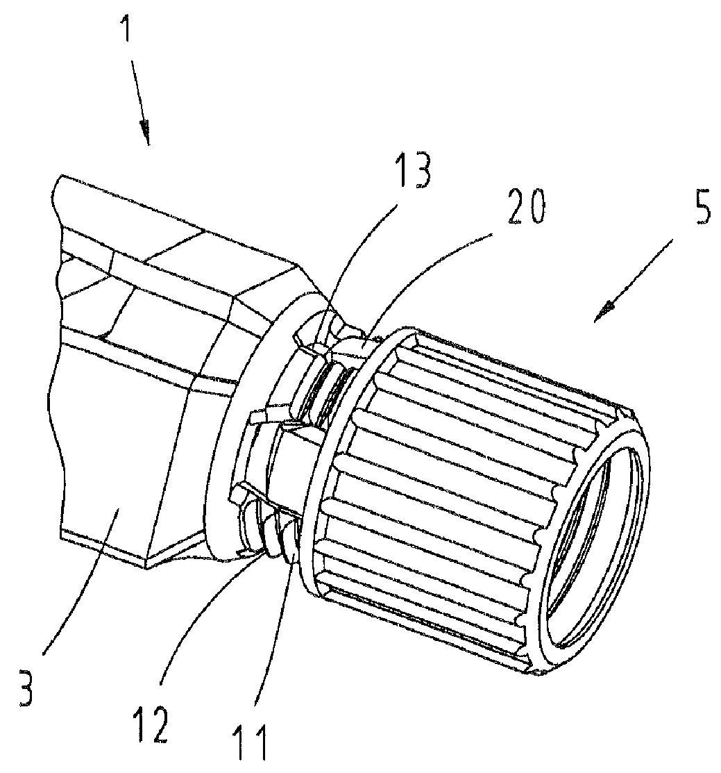
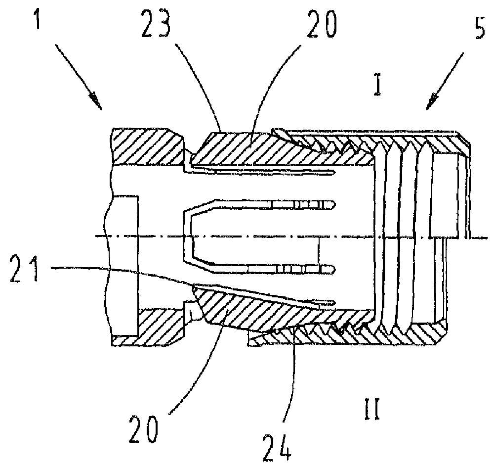
[0030]FIG. 1 shows a three-dimensional representation of a connector housing 1 with a pressure screw 5 partially screwed thereon. A contact area 3 that serves for accommodating contact elements is illustrated in the part of the connector housing 1 shown on the left side. In the region of the connector housing 1 illustrated on the right side, the connection area formed by an integral receptacle sleeve 10 follows the contact area 3.

[0031]The receptacle sleeve 10 serves for accommodating an electrical cable 2 that is inserted into the connector housing 1 and connected to the contact elements. The cylindrical receptacle sleeve 10 is provided with a thread 11, onto which a pressure screw 5 can be screwed. Recesses 13 are provided in and distributed over the circumference of the receptacle sleeve 10, wherein a clamping element 20 is respectively arranged in said recesses. In this case, the clamping elements 20 partially protrude radially beyond the outside diameter 12 of the thread 11 suc...


PUM


Abstract

In a connector housing with integrated cable clamp, it is proposed to provide a receptacle sleeve for an electrical cable that is integrally formed on the connector housing and provided with clamping elements that are distributed over the radius and point in the mating direction. When a pressure screw is screwed onto the receptacle sleeve, the clamping elements are pressed radially inward and the electrical cable is clamped in position.

Description

BACKGROUND OF THE INVENTION[0001]1. Field of the Invention[0002]The invention pertains to a device for clamping an electrical cable connected to a connector, wherein said device consists of a connector housing with an integral receptacle sleeve for the cable that is provided with a thread and at least one clamping element.[0003]A device of this type is required for clamping a cable that is connected to contact elements of a connector and for fixing said cable in the connector housing. This serves for absorbing tensile loads on the cable of the connector and for the strain relief of the contact terminals of the connector, on which the cable is contacted.[0004]2. Description of the Related Art[0005]A few solutions for fixing cables on connectors are already known from the state of the art.[0006]U.S. Pat. No. 6,284,973 discloses a strain relief device for a cable that consists of a base with a tubular extension. The tubular extension features a plurality of flexible arms that can be co...

Claims


Application Information

Patent Timeline
Patent Type & Authority Patents(United States)
IPC IPC(8): H01R13/58
CPCH01R13/5829H01R13/59
Inventor LINDKAMP, MARCKOHLER, ANDREAS
Owner HARTING ELECTRIC GMBH & CO KG
Why Eureka
Try Eureka