

Diaphragm valve
一种膜片阀、膜片的技术,应用在隔膜阀、隔膜、阀细节等方向,能够解决影响寿命、高应力等问题,达到高密封质量的效果
- Summary
- Abstract
- Description
- Claims
- Application Information
AI Technical Summary
Problems solved by technology
Method used
Image

Examples
Embodiment Construction
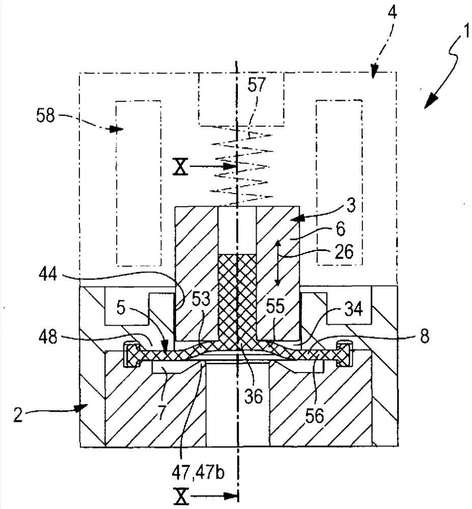
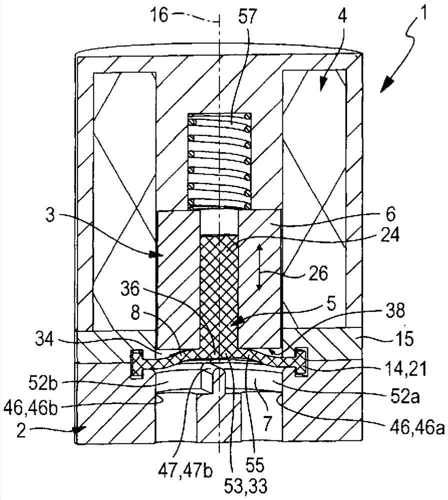
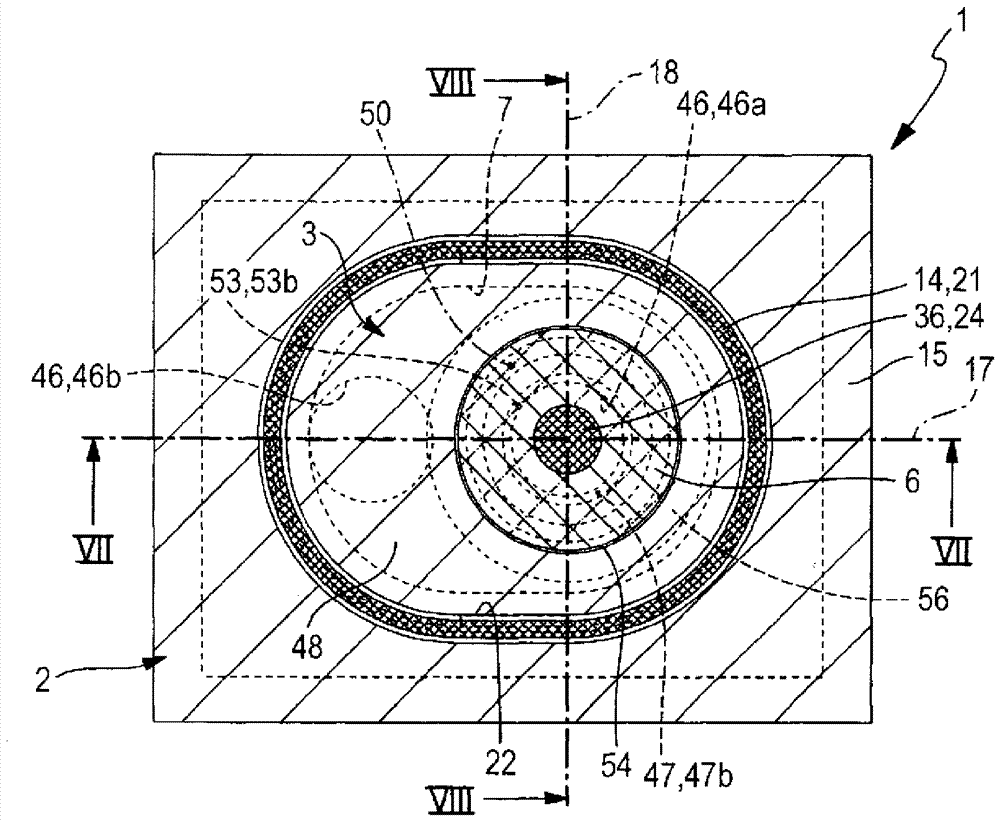
[0038] In all exemplary embodiments, the diaphragm valve, which is designated as a whole by the reference numeral 1 , has a valve housing 2 and a valve part 3 arranged in the valve housing 2 that is movable relative to the valve housing 2 . Furthermore, the diaphragm valve 1 is equipped with an electrically actuatable drive means 4 , preferably arranged in the interior of the valve housing 2 , by means of which the valve part 3 can be switched between two possible switching positions. figure 1 and 2 And 7 and 8 correspondingly show the first switching position, which is the closed position. Figures 4 to 6 And 10 and 11 correspondingly show the second switching position, which is for example the open position.
[0039] The valve part 3 is preferably designed as a composite element consisting of a membrane body 5 and at least one membrane carrier 6 carrying the membrane body 5 . These components are fixed to one another in a manner that will be explained further. Whereas the...
PUM
 Abstract
Description
Claims
Application Information