Pre-stressed implant

a pre-stressed, implant technology, applied in the field of orthopaedic implants or prostheses, can solve the problems of insufficient space to increase the cross-section of implants, the concentration of stress in the region between the stem and the head portion of smaller implants can become problematic, and the implant is particularly susceptible to mid-stem fractures, so as to reduce compressive load, improve stability, and strengthen the effect of implants

Inactive Publication Date: 2006-11-16
DEPUY PROD INC
View PDF18 Cites 0 Cited by
  • Summary
  • Abstract
  • Description
  • Claims
  • Application Information

AI Technical Summary

Benefits of technology

[0007] In order to meet the need for stronger and more durable implants, the present invention contemplates a pre-stressed implant that is especially suited to endure high cyclic tensile loading. In one aspect of the invention, a tension member is fixed within a bore of the implant. This tension member places the implant in compression. When the implant is subjected to loads, the resulting tensile forces acting on the implant act, at least initially, to reduce the compressive load that is generated on the implant by the tension member. In other words, the applied tensile forces de-compress the implant before the implant experiences any meaningful tensile loads. The implant can readily withstand the compressive loads exerted on it by the tension member without any significant risk of failure or fatigue. Moreover, pre-stressing the implant opens up the universe of acceptable materials for the construction of the implant. For instance, the implant can be formed of a high strength ceramic in lieu of the typical metal alloy.
[0012] It is an important object of the invention to improve the strength and fatigue resistance of an orthopaedic implant or prosthesis. One benefit achieved by the present invention is that it reduces the tensile stress experienced by the implant. This benefit manifests itself in longer life for the implant.

Problems solved by technology

Stress concentrations in the region between the stem and head portions of smaller implants can become problematic.
Smaller implants are particularly susceptible to mid-stem fractures.
Consequently, there is no room to increase the cross-section of the implants to add strength.

Method used


Image

  • Pre-stressed implant
  • Pre-stressed implant
  • Pre-stressed implant

Examples


Embodiment Construction

[0024] For the purposes of promoting an understanding of the principles of the invention, reference will now be made to the embodiments illustrated in the drawings and described in the following written specification. It is understood that no limitation to the scope of the invention is thereby intended. It is further understood that the present invention includes any alterations and modifications to the illustrated embodiments and includes further applications of the principles of the invention as would normally occur to one skilled in the art to which this invention pertains.

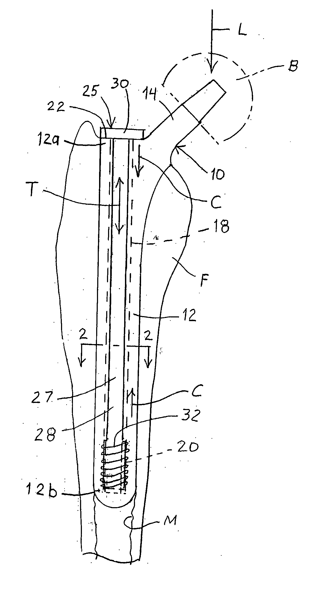
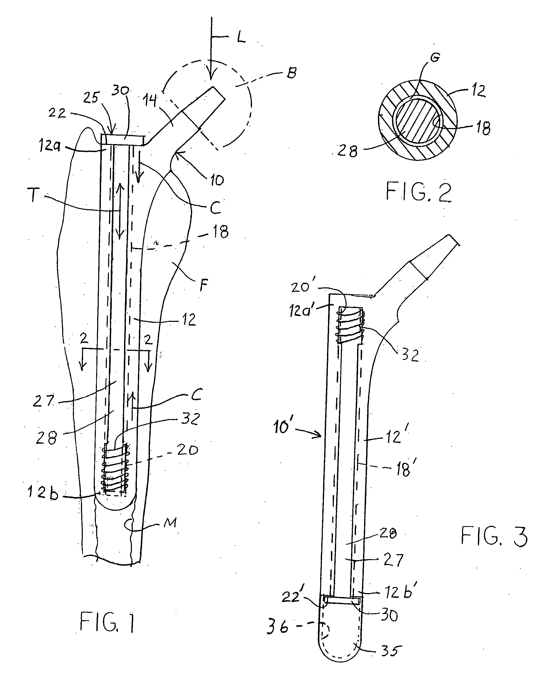
[0025] In one embodiment of the invention, an implant or prosthesis 10 is disposed within a bone, such as the femur F, as shown in FIG. 1. The implant includes a stem 12 that is engaged within the medullary canal M of the femur. The implant 10 further includes a neck 14 extending from the stem at an appropriate angle dictated by the anatomy of the hip joint. The neck 14 is configured to receive an articulating...


PUM


Abstract

A pre-stressed orthopaedic implant includes a tension member extending through a bore in the implant. The tension member can include a bolt that is tightened into threads at the closed end of the bore, thereby compressing the implant between the bolt head and the threaded engagement. The implant is fixed within a bone while the implant is maintained in compression to improve the implant's ability to withstand tensile loads.

Description

[0001] This application is a continuation of co-pending application Ser. No. 10 / 742,294, filed on Dec. 19, 2003, the disclosure of which is hereby totally incorporated by reference in its entirety.BACKGROUND OF THE INVENTION [0002] The present invention relates to orthopaedic implants or prostheses, and particularly to implants subjected to high tensile loads. The invention has particular application to implants or prosthesis that form part of a joint of the human body, such as the hip, knee or shoulder. [0003] Implants or joint prostheses have improved significantly over the last few decades, largely due to improvements in the bio-compatibility, strength and durability of the implant materials. New machining processes and material coatings have been developed that enhance the fixation of the implant within the natural bone of a patient. Alloys and ceramics have been developed that emulate the strength of natural bone, while still preserving the biomechanical attributes of the joint...

Claims


Application Information

Patent Timeline
Patent Type & Authority Applications(United States)
IPC IPC(8): A61F2/36A61F2/28A61F2/00A61F2/02A61F2/30A61F2/38A61F2/40A61F2/46
CPCA61F2/30744A61F2310/00011A61F2/3662A61F2/367A61F2/3672A61F2/3676A61F2/38A61F2/3804A61F2/40A61F2002/30332A61F2002/30405A61F2002/30449A61F2002/30462A61F2002/30492A61F2002/30509A61F2002/3051A61F2002/30512A61F2002/30514A61F2002/30546A61F2002/30568A61F2002/30589A61F2002/30616A61F2002/30797A61F2002/3611A61F2002/3625A61F2002/3647A61F2002/365A61F2002/3694A61F2002/4638A61F2002/465A61F2220/0025A61F2220/0033A61F2220/005A61F2220/0075A61F2250/0012A61F2/36A61F2002/30507
Inventor SOUTHWORTH, CARLETON B.TOMASZEWSKI, PAUL
Owner DEPUY PROD INC
Why Eureka
Try Eureka