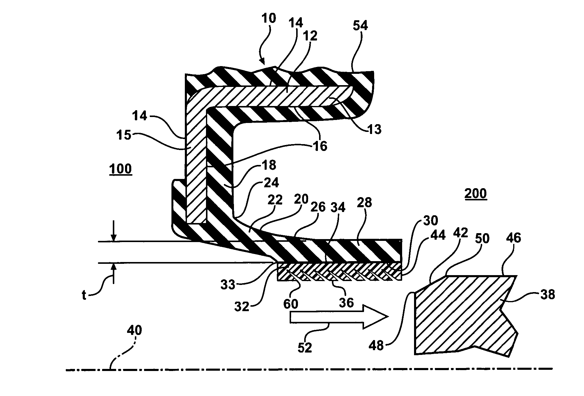
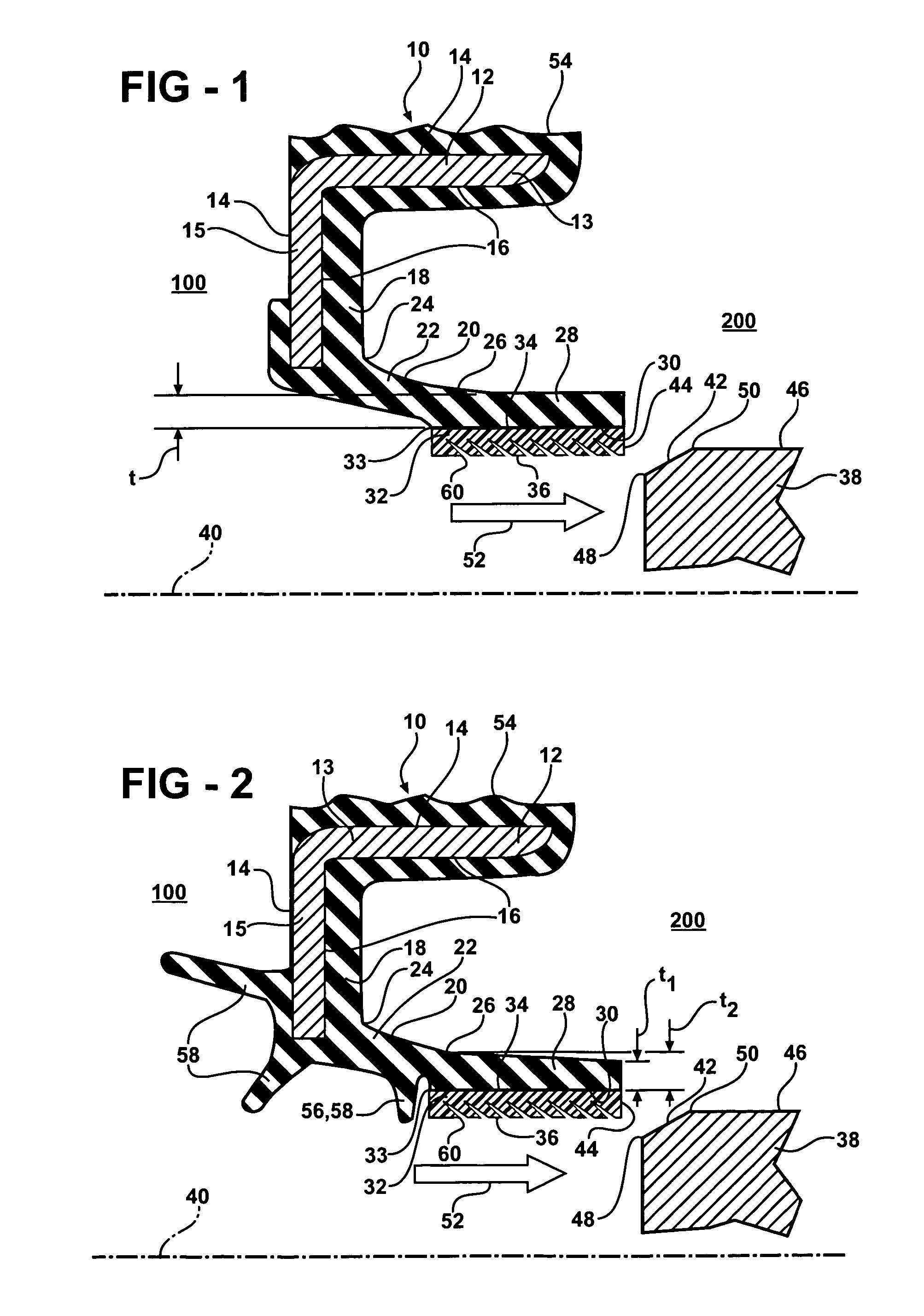
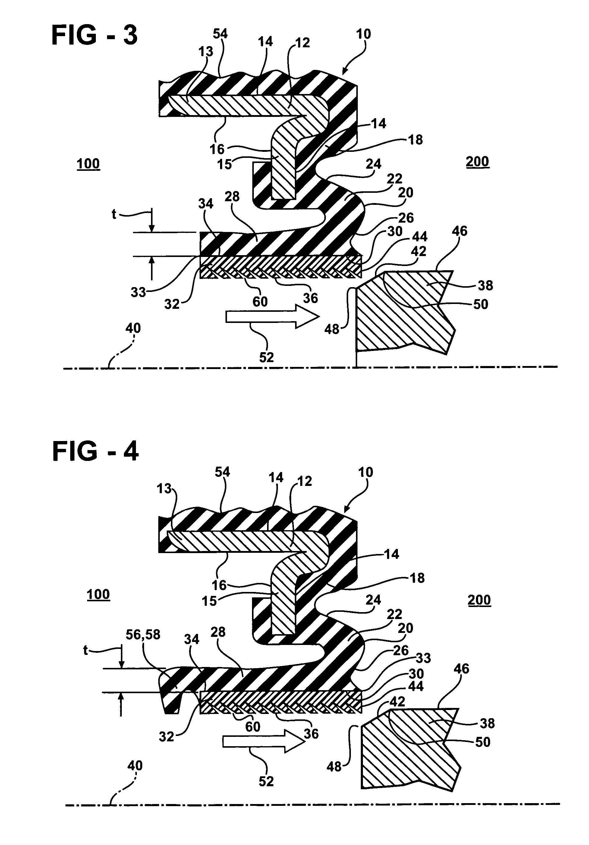
[0010] The present invention is a radial seal, such as a radial shaft seal, having a fluoropolymer sealing element which is bonded to an elastomeric casing which is in turn bonded to a rigid casing, such as a rigid
metal casing. Radial seals of the present invention may also incorporate additional features molded into the elastomeric casing such as
dirt exclusion lips and static air seals which may further enhance installation, testing (i.e.,
air leak testing) or operation of the seals.
[0012] In a second aspect of the invention, the neck portion may have any one of a number of shapes or profiles, including a generally linear profile, curvilinear profile,
bellows profile, or any one of a number of other known shapes or profiles. This provides the
advantage of being able to tailor the spring and other characteristics of the axial spring member (i.e., force, flexibility and followability), including the neck and the attachment portions of the elastomeric casing.
[0014] In a fourth aspect of the invention, the fluoropolymer sealing element may optionally incorporate various sealing features in the bonding surface of the fluoropolymer element, including, threaded or other continuous groove patterns, or patterns of one or more circumferential grooves or channels or other discontinuous groove patterns, or combinations of the above. These groove patterns may have a uniform depth or variable depth along the length of the fluoropolymer element. The grooves may also alternately constitute raised ribs. These grooves provide the
advantage of enhancing the retention of the fluid, such as oil, which is to be sealed by the action of the radial seal, such as by providing a hydrodynamic pumping action of the fluid in conjunction with the rotation of the sealing surface.
[0015] In a fifth aspect of the invention, the radial seal may optionally include an air lip or seal into the elastomeric casing on the air side of the radial seal. This seal is preferably a static seal, but may also be used in the context of a transient or temporary dynamic seal for a limited duration, such as initial or in-process testing during the manufacture and / or use of the device which incorporates the radial seal. In the context of an
internal combustion engine, this provides the
advantage of in-process pressure testing of the engine during the engine manufacturing and
assembly process, and facilitate acceptance or rejection of the engine, without the need to also provide temporary or in-process seals on the shaft surface to be sealed by the radial seal in order to facilitate this testing.
[0017] In a seventh aspect of the invention, the pre-stressed fluoropolymer element will generally have a
stress profile that varies in magnitude longitudinally along the length of the fluoropolymer element. Advantageously, this
stress profile may be tailored by controlling the thickness and / or thickness profile of the element, along with the amount of pre-stressing the PTFE element is subjected to after stretching the element into its final location in the mold. Further, the method of stretching the fluoropolymer element allows the element to be oriented with the
stress profile in one of two orientations, one being the inverse of the other, based on how the stretched seal is loaded into a mold with the other elements of the radial seal.
[0018] In an eighth aspect of the invention, the radial seal of the present invention may be configured in either a standard or a reverse lay-down configuration. In either configuration, the radial seal of the present invention is believed to be less susceptible to potential seal damage issues associated with installation of the seals on a shaft or other surface to be sealed. In fact, the configuration of the radial seal of the present invention reduces the distinction between the traditional installation configuration and a reverse lay-down installation configuration seals by virtue of the fact that it has fundamentally two free ends and thus, it has less of a distinction with regard to whether the seal is installed first from the free end than related art seal designs. It presents more of a bi-directional lay-down configuration. Further, this feature can be combined with the ability to orient the pre-
stress level in the fluoropolymer element such that the highest level of pre-stress and thus the greatest sealing force is applied to the surface to be sealed either closer to or farther from the installation end of the seal. For example, the fluoropolymer element may be located in the seal with the pre-
stress level profile oriented such that the sealing force applied to the sealing surfaces is lower closer to the installation end in order to promote the installation of the seal.

