Concentrating solar collector

a solar collector and concentrating technology, applied in the direction of solar heat collectors, solar-ray concentration, moving/orienting solar collectors, etc., can solve the problems of reducing the accuracy with which the module needs to be aligned with the sun, increasing stiffness, etc., and achieves uniform cross section, stable mounting, and stable mounting

Inactive Publication Date: 2009-03-12
WHITFIELD SOLAR
View PDF31 Cites 32 Cited by
  • Summary
  • Abstract
  • Description
  • Claims
  • Application Information

AI Technical Summary

Benefits of technology

[0008]A concentrating solar collector having such concentrating solar collector modules has a number of advantages. In particular, the trough can have a comparatively large surface area per lens in comparison to a housing incorporating a two dimensional array of lenses. For example, if a module has a square cross section, the surface area of the each of the sides and base of the trough are each roughly the same as the surface area of all the lenses together. So, the surface area of the trough can be approximately three times the surface area of the lenses (ignoring the ends of the trough). On the other hand, for a housing of comparable depth incorporating a large two dimensional array of similar lenses, the surface area of the sides of the housing is small in comparison to the surface area of all of the lenses. So, the housing of such a large two dimensional array has almost the same surface area (that of its base) as the surface area of the lenses. One advantage of the invention is therefore that the concentrating solar modules can have a comparatively large ratio of total surface area to surface area of the lenses, which means that the concentrating solar collector can be significantly better at dissipating heat. Similarly, problems associated with thermal or humidity related expansion and contraction of the modules are alleviated by use of a single row of lenses rather than a two dimensional array, as only expansion and contraction along the length of the row has any significant effect. The trough also tends to be more rigid than a comparable housing for a two-dimensional array of lenses. It therefore requires less material or reinforcement to be sufficiently stiff to withstand wind loading and such like. This reduces manufacturing costs and can make the module lighter, which can improve portability and ease of installation. Increased stiffness can also reduce the accuracy with which the module needs to be aligned with the sun, as less stiff designs need to be aligned with the sun sufficiently accurately to tolerate variations in alignment of different lenses due to bending and twisting of the structure supporting them.
[0009]Solar cells should ideally be mounted at the regions along the inside of the trough at which the lenses focus the light. It will be appreciated that the lenses should continue to focus light to these regions regardless of the position of the sun in the sky. So, the concentrating solar collector modules are typically mounted so that they can rotate to track the azimuth and elevation of the sun in the sky. This tends to be simplest if the concentrating solar collector modules are arranged roughly parallel to one another.
[0010]For example, each concentrating solar collector module is usually mounted so that it can rotate around a rocking axis substantially parallel to its longitudinal axis. Preferably, the rocking axis of each concentrating solar collector module passes through the volume of the trough of the respective module. Most preferably, it is the major axis of the module. This allows the modules to each rotate separately and to be stably mounted. The solar collector modules are also usually mounted so that they can rotate around a pitch axis perpendicular to their longitudinal axes and in a direction from one side of the trough to another. The pitch axis usually substantially bisects the troughs of the solar collector modules, again allowing the modules to be stably mounted.
[0011]Rotation of the modules usually requires electrical power. The concentrating solar collector preferably therefore has a photovoltaic flat panel for generating electricity for use by the collector. The photovoltaic flat panel can be mounted on a dummy module. So, the solar collector may have a dummy module, of similar dimensions to the solar collector modules, for housing an apparatus for controlling rotation of the solar collector modules. The dummy module and the solar collector modules may have the same orientation and are arranged to rotate together, and the apparatus comprises a sensor for detecting the direction of the sun. The apparatus may also include a motor for driving the rotation of the solar collector modules.
[0012]The trough may have various shapes. It preferably has a uniform cross section. This cross section might be rectangular or square for example, so that the trough is box shaped. However, it is preferred that the trough is roughly V shaped in cross section. This increases the stiffness of the trough. The uniform cross section also allows the trough to be an extrusion. The method of manufacture may therefore include extruding the trough.
[0013]The lenses are usually Fresnel lenses, as these are relatively thin and lightweight in comparison to other types of lenses. This allows the row of lenses comprises a single sheet of material. However, in other examples, the lenses might be simple lenses, compound lenses, aspheric lenses, stepped lenses (such as Buffon lenses) or another form of light converging devices. They should be roughly circularly symmetric, as it is desirable for the concentrating solar collector to concentrate light to regions both toward a narrow part of the width of the trough and spaced apart from one another along the length of the trough. The regions are preferably spaced along the centre of the length of the base of the trough. Indeed, the regions are preferably at positions substantially coaxial with the axes of symmetry of the lenses. Similarly, the solar cells are preferably mounted on the inside surface of the base of the trough at positions substantially coaxial with the axes of symmetry of the lenses. Whilst any practical design that concentrates light to separate regions can be considered substantially circularly symmetric for the purpose of the invention, ideally the lenses are substantially or even exactly circularly symmetrical.

Problems solved by technology

Increased stiffness can also reduce the accuracy with which the module needs to be aligned with the sun, as less stiff designs need to be aligned with the sun sufficiently accurately to tolerate variations in alignment of different lenses due to bending and twisting of the structure supporting them.

Method used


Image

  • Concentrating solar collector
  • Concentrating solar collector
  • Concentrating solar collector

Examples


Embodiment Construction

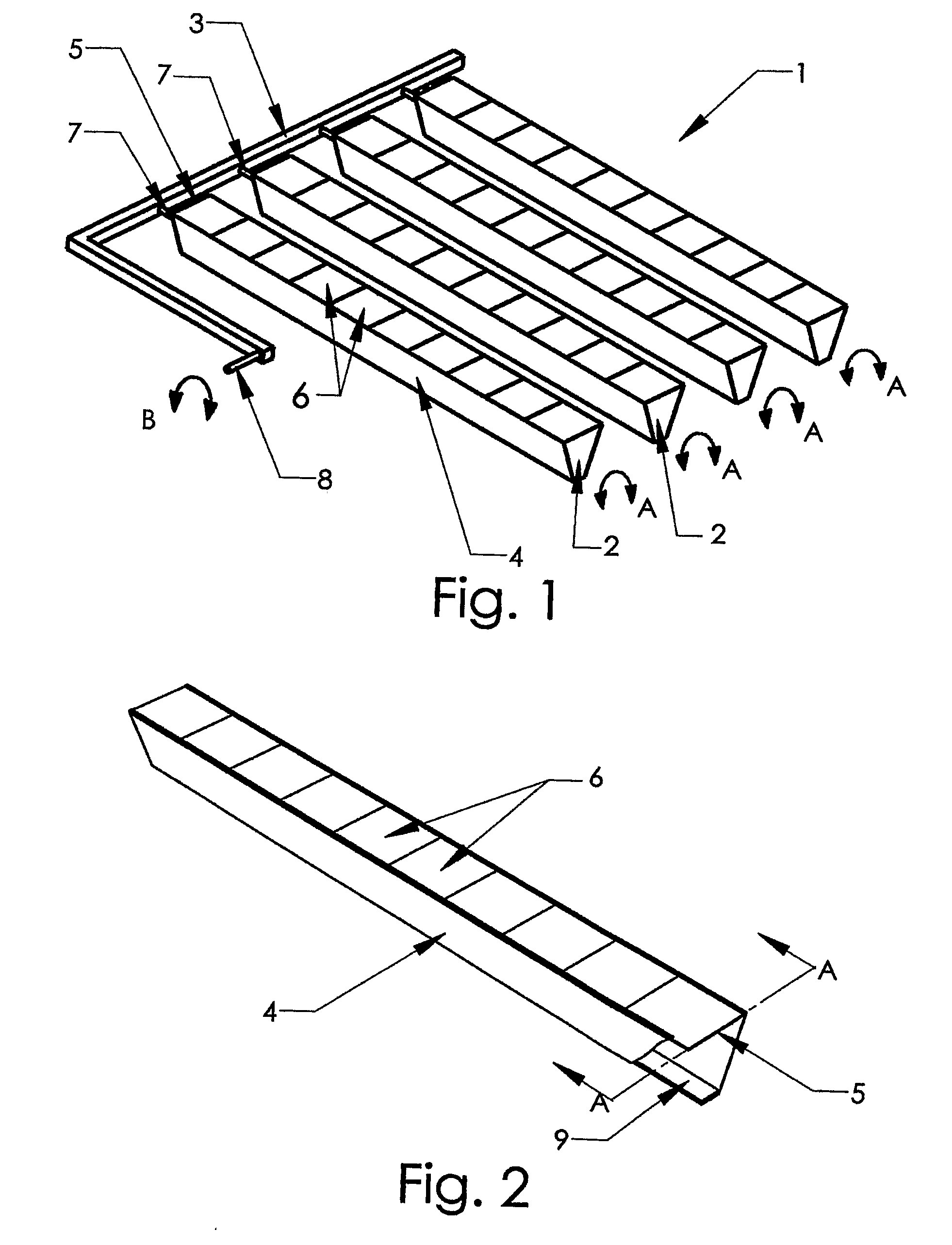
[0037]Referring to FIG. 1, a concentrating solar collector 1 comprises concentrating solar collector modules 2 mounted on a frame 3. The number of concentrating solar collector modules 2 can vary. The concentrating solar collector I is shown in FIG. 1 with four concentrating solar collector modules 2, but the collector 1 can have more or less than four modules 2 in other embodiments. Indeed, typically the concentrating solar collector 1 has around twelve concentrating solar collector modules 2.

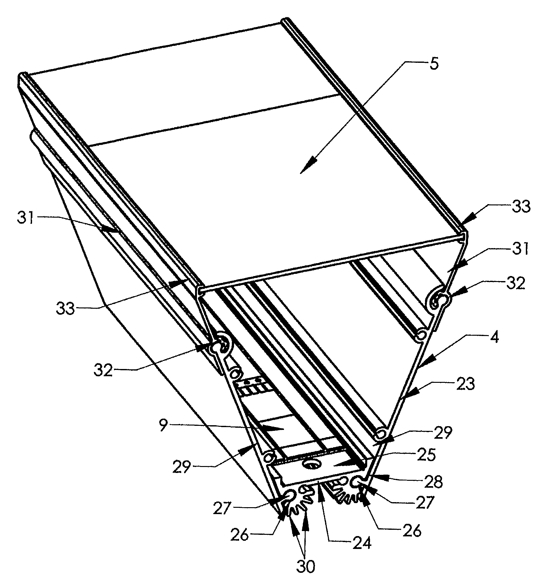
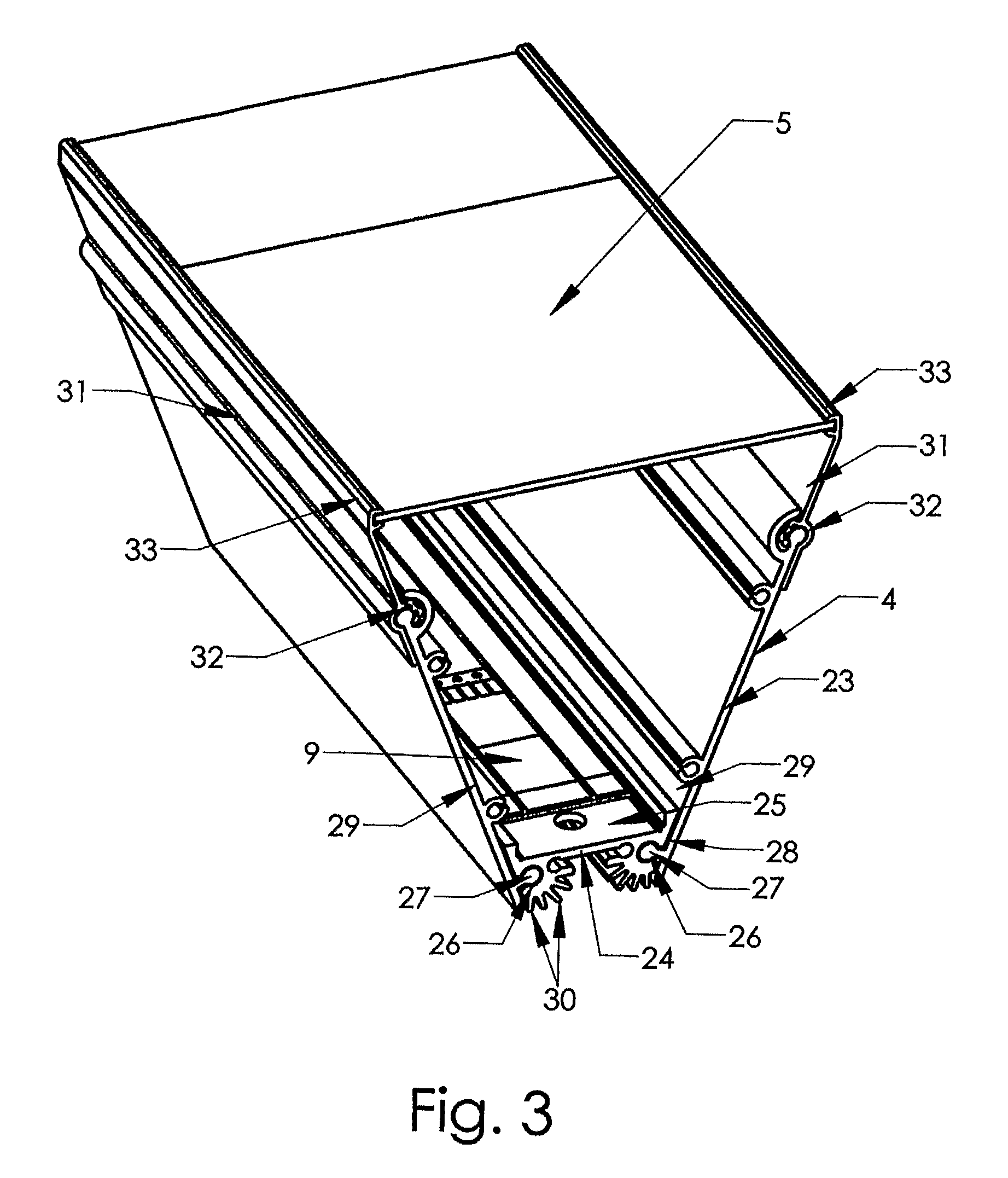
[0038]Each concentrating solar collector module 2 comprises a trough 4 with a lens sheet 5 over its open face. The troughs 4 are roughly V shaped. More specifically, the troughs 4 each have a cross section that is substantially V shaped with a truncated (or flattened) base. In other words, the troughs 4 are narrower at their base than at their open face. This can help to make the troughs 4 more rigid than comparable box or U shaped designs. The troughs 4 also have a uniform cross section along...


PUM


Abstract

A concentrating solar collector comprises concentrating solar collector modules mounted on a frame. Each concentrating solar collector module comprises a trough with a lens sheet over its open face. The troughs each have a cross section that is substantially V shaped with a truncated (or flattened) base. The lens sheet incorporates a linear array of ten lenses in a row along its length. Each lens of the lens sheet is a circularly symmetric Fresnel lens. The concentrating solar collector modules can each rotate about a rocking axis parallel to their length. The concentrating solar collector modules can also rotate about a pitch axis substantially at their midpoints. This allows the lenses to track the position of the sun in the sky.

Description

FIELD OF THE INVENTION[0001]This invention relates to a concentrating solar collector. In particular, the invention relates to a concentrating solar collector comprising multiple concentrating solar collector modules and to methods of manufacturing the same.BACKGROUND TO THE INVENTION[0002]Concentrating solar collectors can be used to collect solar radiation for heating or electricity generation. In the case of electricity generation, they incorporate solar cells, which are able to convert solar radiation, or more plainly “light”, received at the concentrating solar collector into electricity. They are described as concentrating as they concentrate light onto the solar cells using lenses or mirrors. This reduces the area of solar cells needed to convert a given amount of light into electricity.[0003]Given current interest in renewable sources of energy, there is a general desire to improve accessibility to solar electricity generation by making solar electricity generation cheaper. ...

Claims


Application Information

Patent Timeline
Patent Type & Authority Applications(United States)
IPC IPC(8): F24J2/08H02N6/00F24J2/54F24S23/30
CPCF24J2/085F24J2/5424Y02E10/43H01L31/0547Y02E10/52H01L31/0543Y02E10/47F24S30/455F24S23/31
Inventor WEATHERBY, CLIVE KEITHBENTLEY, ROGER WILLIAM
Owner WHITFIELD SOLAR
Why Eureka
Try Eureka