Elastic-wave filter device

a filter device and elastic wave technology, applied in the direction of piezoelectric/electrostrictive/magnetostrictive devices, electrical apparatus, impedence networks, etc., can solve the problems of increasing potential difference, fig. 19, and unable to direct connect a plurality of ground pattern elements to a plurality of external connection terminals provided on the side surfaces of the package substrate, etc., to achieve a degree of balance, higher range, and higher range

Active Publication Date: 2012-10-09
MURATA MFG CO LTD
View PDF15 Cites 0 Cited by
  • Summary
  • Abstract
  • Description
  • Claims
  • Application Information

AI Technical Summary

Benefits of technology

[0008]To overcome the problems described above, preferred embodiments of the present invention provide an elastic-wave filter device capable of improving out-of-band attenuation in a higher range than the pass band without deteriorating the insertion loss within the pass band even when the size of the elastic-wave filter device is reduced.
[0011]Accordingly, out-of-band attenuation in a higher range than the pass band can be effectively improved without deteriorating the insertion loss within the pass band.
[0017]In this case, among the first via conductors connecting the ground pattern element and the internal ground pattern element, of the first via conductors connected to the two output pattern elements, the number of first via conductors arranged at a first side with respect to the center line with a greater distance from the center line is greater than that at a second side with respect to the center line. This enables separation and concentration of a current that flows between the ground pattern element and the internal ground pattern element to be adjusted to perform optimization so as to have a large amount of out-of-band attenuation.
[0019]In this case, even with a small size, the out-of-band attenuation in a higher range than the pass band can be improved without deteriorating the degree of balance within the pass band.
[0024]With this configuration, for the reception band pass filter of the duplexer, out-of-band attenuation in a higher range than the pass band is improved without deteriorating the insertion loss and the degree of balance within the pass band.
[0025]With various preferred embodiments of the present invention, even with a small size, the out-of-band attenuation in a higher range than the pass band is effectively improved without deteriorating the insertion loss within the pass band.

Problems solved by technology

However, with the advancement of miniaturization of products, directly connecting a plurality of ground pattern elements to a plurality of external connection terminals provided on side surfaces of the package substrate, as illustrated in FIG. 19, becomes impossible.
This results in an increased potential difference between the potential of the ground pattern element and the reference potential surface, which leads to an increase in high-frequency current produced as a result of a parasitic component.

Method used


Image

  • Elastic-wave filter device
  • Elastic-wave filter device
  • Elastic-wave filter device

Examples


first preferred embodiment

[0049]An elastic-wave filter device 10 according to a first preferred embodiment of the present invention is described with reference to FIGS. 1 to 9.

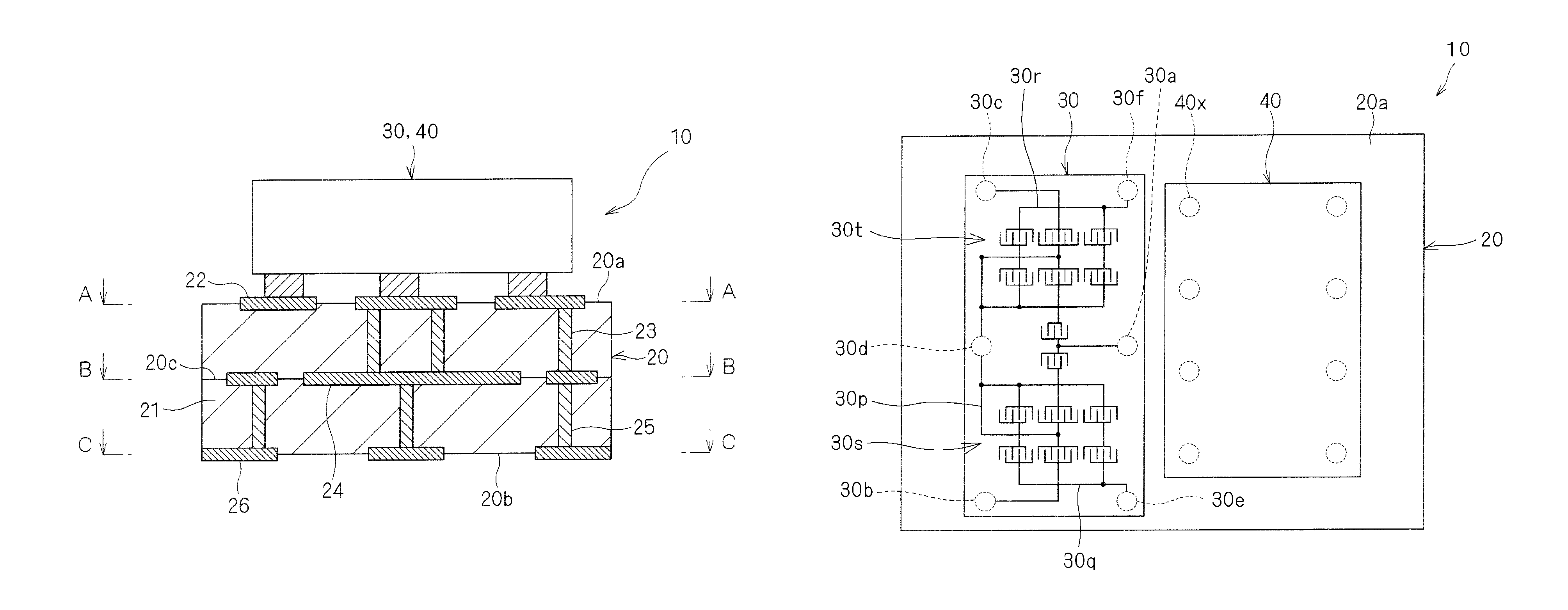
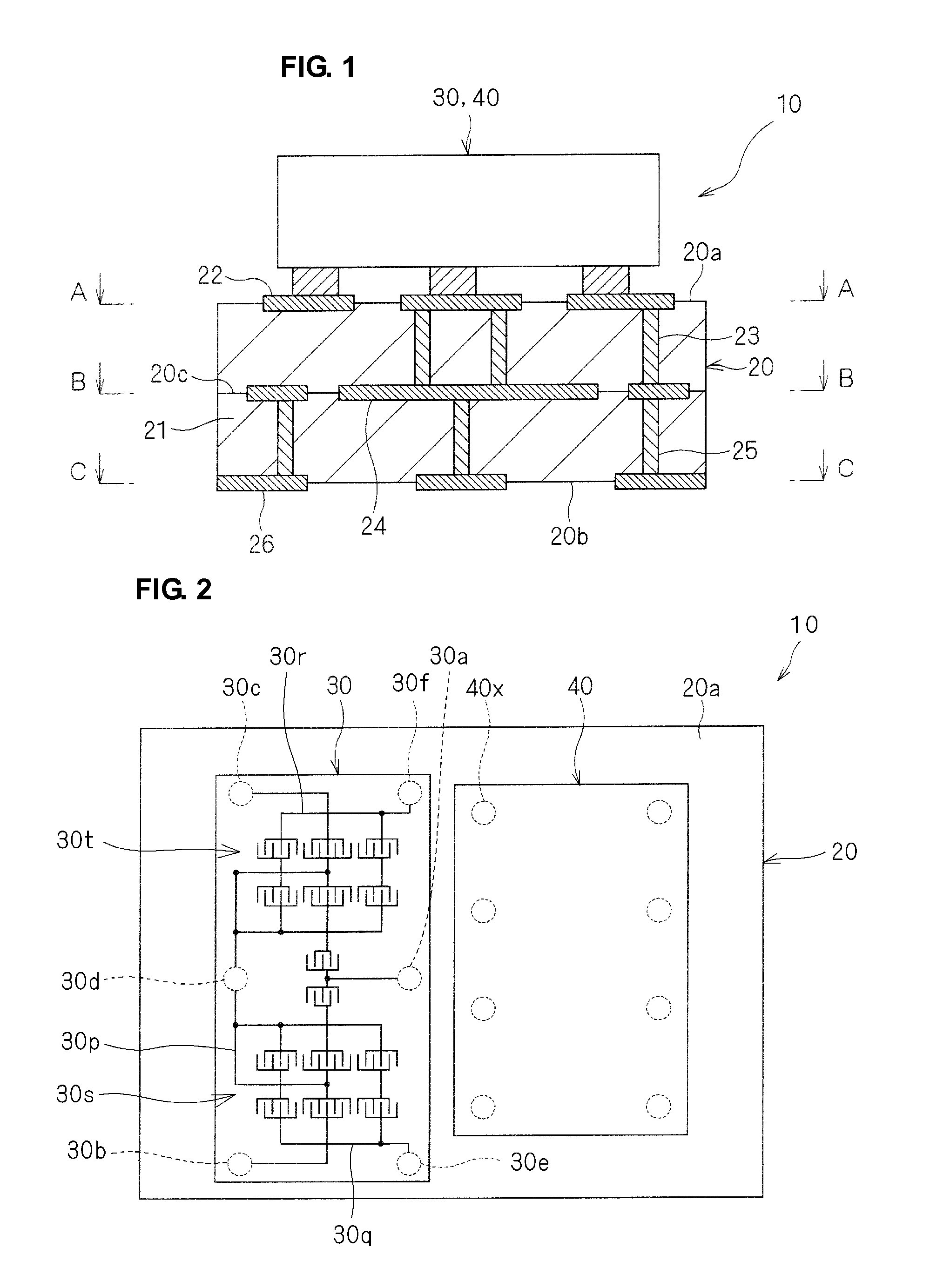
[0050]FIG. 1 is a cross-sectional view of the elastic-wave filter device 10. FIG. 2 is a plan view of the elastic-wave filter device 10 and schematically illustrates an internal configuration of a reception filter 30.

[0051]As illustrated in FIGS. 1 and 2, the elastic-wave filter device 10 is preferably a duplexer in which the reception filter 30 and a transmission filter 40 are mounted on a package substrate 20. For example, the reception filter 30 may preferably be a longitudinally coupled resonator-type surface-acoustic-wave (SAW) filter, and the transmission filter 40 may preferably be a surface-acoustic-wave (SAW) filter having a ladder circuit.

[0052]The package substrate 20 is preferably a composite substrate that includes a plurality of insulation layers and a conductive pattern provided therebetween. Specifically, in the package...

second preferred embodiment

[0089]An elastic-wave filter device according to a second preferred embodiment of the present invention is described with reference to FIGS. 10A to 15C.

[0090]The elastic-wave filter device according to the second preferred embodiment has substantially the same configuration as that according to the first preferred embodiment, except for the configuration for the reception filter of the package substrate. In the following, the description is directed primarily to differences from the first preferred embodiment, and the same reference numerals are used as in the first preferred embodiment for the same components.

[0091]FIG. 10A is a plan view of the filter mounting surface 20a of the package substrate. In FIG. 10A, the cross symbols schematically indicate the locations of the pads of each of the reception filter and the transmission filter. The solid circle symbols schematically indicate the locations of the first via conductors provided between the filter mounting surface and the inte...

third preferred embodiment

[0109]An elastic-wave filter device according to a third preferred embodiment of the present invention is described with reference to FIGS. 16A to 17.

[0110]The elastic-wave filter device according to the third preferred embodiment differs from that in each of the first and second preferred embodiments in that the reception filter is an unbalanced filter.

[0111]FIG. 16A is a plan view of the filter mounting surface 20a of the package substrate. In FIG. 16A, the cross symbols schematically indicate the locations of the pads of each of the reception filter and the transmission filter. The solid circle symbols schematically indicate the locations of the first via conductors provided between the filter mounting surface 20a and the internal electrode surface 20c.

[0112]As illustrated in FIG. 16A, the filter mounting pattern 22p preferably having the same or substantially the same shape as in the second preferred embodiment is provided on the filter mounting surface 20a of the package subst...


PUM


Abstract

An elastic-wave filter device includes a package substrate and filter mounting pattern provided on a first main surface of the package substrate on which a longitudinally coupled resonator-type elastic-wave filter is mounted, a back-side terminal pattern is provided on a second main surface thereof, and an internal electrode pattern is provided inside the package substrate. When seen in plan view from a direction perpendicular or substantially perpendicular to the first main surface of the substrate body, first via conductors electrically connecting a ground pattern element of the filter mounting pattern connected to a ground pad of the longitudinally coupled resonator-type elastic-wave filter and an internal ground pattern element of the internal electrode pattern are arranged asymmetrically with respect to a center line X-X passing through an input pattern element of the filter mounting pattern and through two output pattern elements.

Description

BACKGROUND OF THE INVENTION[0001]1. Field of the Invention[0002]The present invention relates to elastic-wave filter devices, and specifically, an elastic-wave filter device that includes a longitudinally coupled resonator-type elastic-wave filter.[0003]2. Description of the Related Art[0004]An elastic-wave filter device in which an elastic-wave filter that utilizes an elastic wave, such as a surface acoustic wave propagating along the surface of a piezoelectric substrate or a boundary acoustic wave propagating along the boundary between a piezoelectric substrate and a solid layer, accommodated in a package, has been proposed. For such an elastic-wave filter device, the degree of out-of-band suppression may be decreased by a parasitic component of the package.[0005]To improve out-of-band suppression, for example, Japanese Unexamined Patent Application Publication No. 11-145772 discloses, as a package on which a surface-acoustic-wave filter is mounted surface-down, a configuration il...

Claims


Application Information

Patent Timeline
Patent Type & Authority Patents(United States)
IPC IPC(8): H03H9/72H03H9/64
CPCH03H9/0085H03H9/0571H03H9/0576
Inventor FUJITA, SHIGEYUKI
Owner MURATA MFG CO LTD
Why Eureka
Try Eureka