Apparatus for controlling the release of a tip-up signal indicator for a trap

a technology of tip-up signal and apparatus, which is applied in fishing, other angling devices, animal husbandry, etc., can solve the problems of obstructing view, false indication of caught fish, and difficult setting, and achieves the effect of easy setting

Inactive Publication Date: 2013-01-01
RAND RICKY
View PDF8 Cites 0 Cited by
  • Summary
  • Abstract
  • Description
  • Claims
  • Application Information

AI Technical Summary

Benefits of technology

The invention is about a reliable fish trap that indicates when a fish is caught without giving false indications. The trap has an elongated crossbeam and mast that can rotate to wind fishing line and hook. There is a trigger rod that can rotate in an arc around its axis and is equipped with a hook and a resilient tip-up signaling indicator. The indicator is connected to a trigger bolt which is used to secure the indicator to the hook. The bolt and indicator are designed to withstand vibration and motion. The trigger hook is designed to engage the indicator and retain it while the trap is in a locked state.

Problems solved by technology

While common, this arrangement suffers from the disadvantage of over sensitivity, as several factors may cause a false indication.
The most common of those factors is wind induced motion and / or vibration, which operates to release the spring, causing a false indication of a caught fish.
These arrangements suffer from the disadvantages of obstructing view within the hole, and poor stability, as well as interfering with access to the ice hole, needed to break newly formed ice.

Method used


Image

  • Apparatus for controlling the release of a tip-up signal indicator for a trap
  • Apparatus for controlling the release of a tip-up signal indicator for a trap
  • Apparatus for controlling the release of a tip-up signal indicator for a trap

Examples


Embodiment Construction

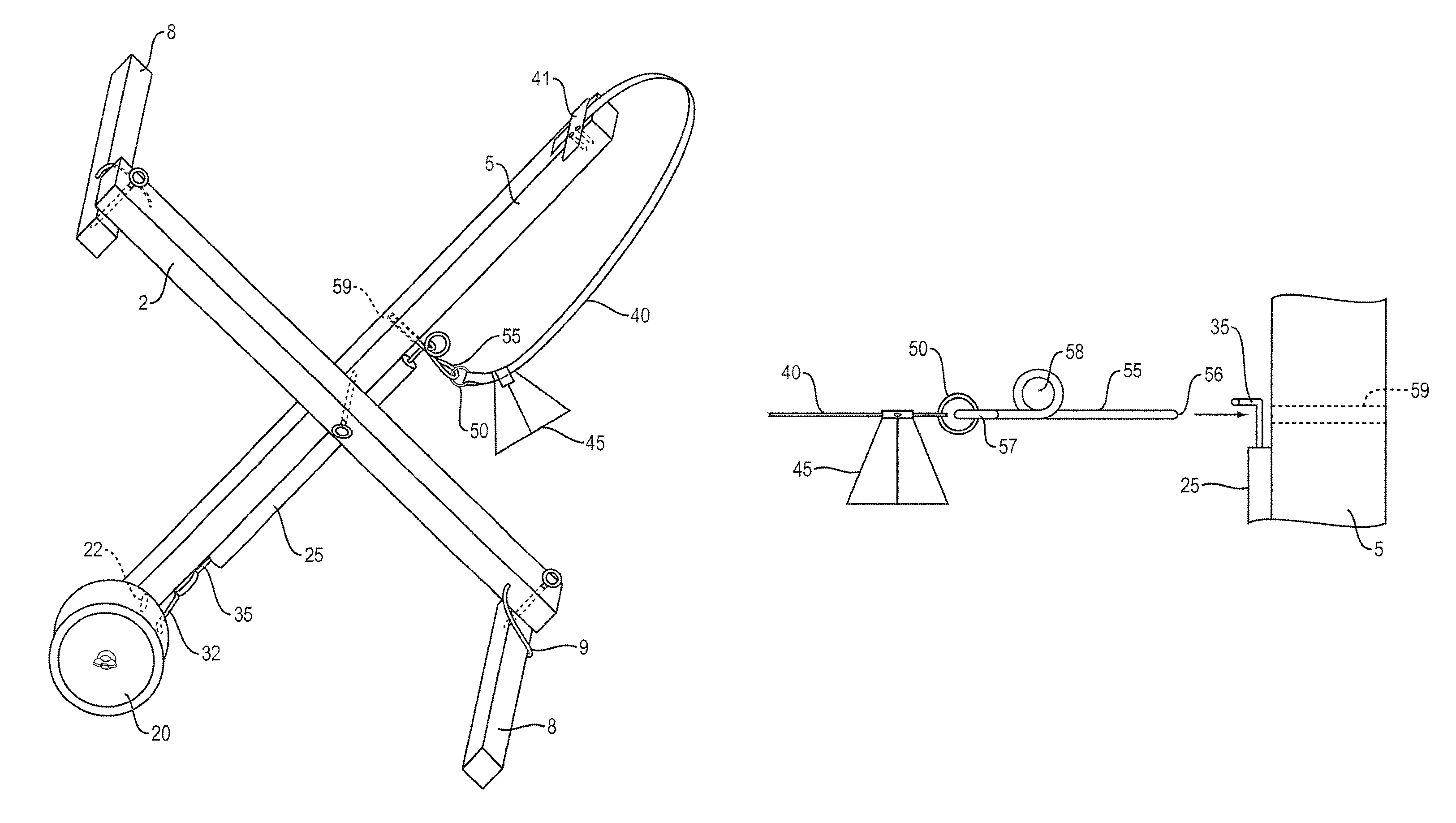
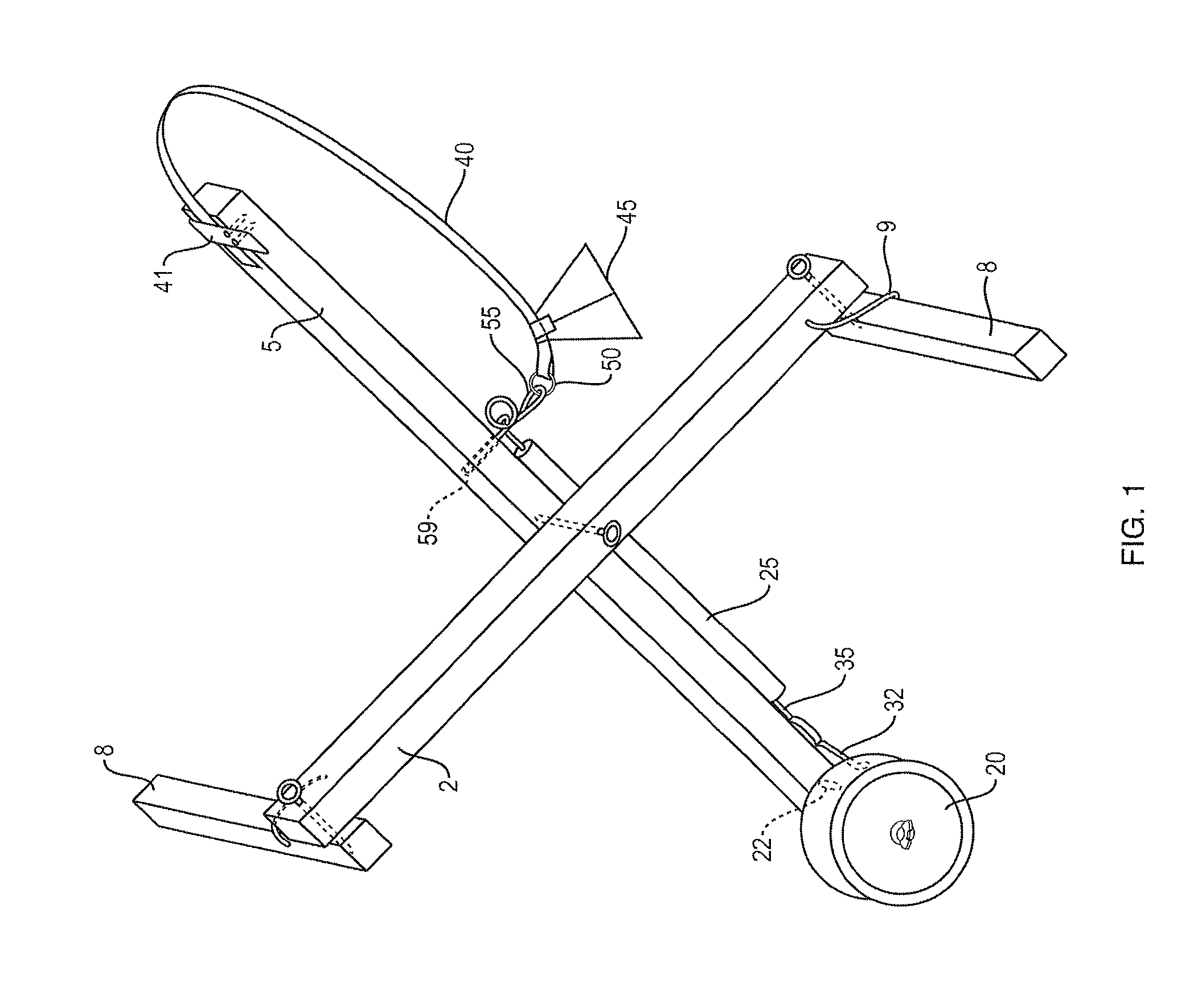
[0028]The preferred embodiment of a fish trap according to the invention comprises a foldable frame, having an elongated crossbeam 2 hingedly coupled to an elongated mast 5. Preferably, the crossbeam and mast are hinged at a hinge point 4 about their mid-length. A stabilizer bar 8 is hingedly coupled at, or adjacent to, each end of the crossbeam 2. Preferably the trap may be folded to reduce its size when not deployed as shown in FIG. 9. Other portions of the trap, and the manner by which they cooperate in various embodiments, will be explained below with reference to various drawings.

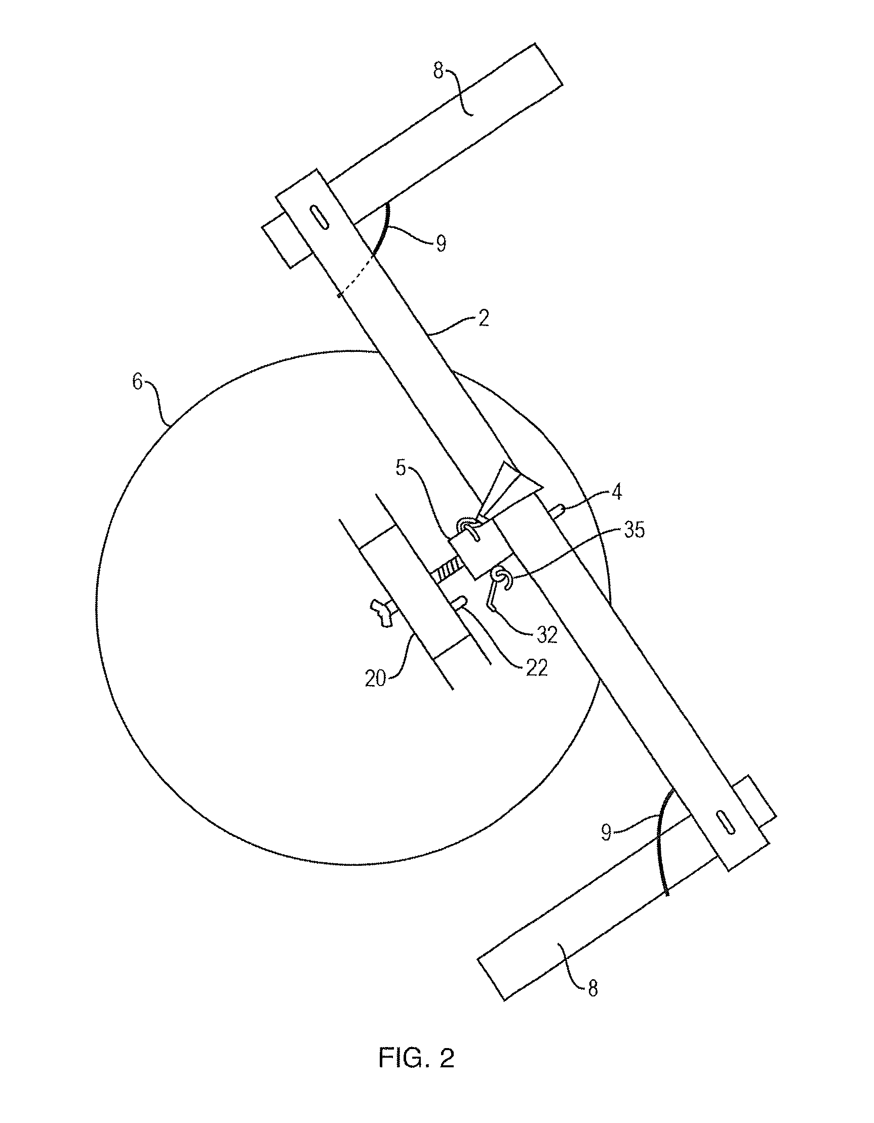
[0029]FIG. 1 depicts a schematic perspective view of the fish trap according to the preferred embodiment of the invention, FIG. 2 depicts a top view thereof, and FIG. 3 depicts a frontal elevation of the trap in operational state indicated a caught fish. In FIGS. 2 and 3 the trap is shown in a deployed disposition over an ice hole 6.

[0030]Crossbeam 2 extends horizontally over the ice hole 6, and stabil...


PUM


Abstract

An ice fishing trap comprising in its operational state a crossbeam dimensioned for extending across a hole in ice covering a body of water, and a hingedly coupled vertical mast. The vertical mast has a rotatable reel dimensioned to carry a length of fishing line and a hook. A trigger mechanism is provided, wherein a rotation of the reel causes an arcuate movement of a trigger hook. One aspect of the invention provides at least two stabilizer limbs hingedly coupled to the crossbeam, so as to form a general Z shaped support base when operational. In another aspect the fishing trap provides a trigger bolt coupled to an indicator spring, wherein the trigger bolt is utilized to couple the indicator spring to the trigger hook. The trigger bolt is slidingly supported by bolt guide, thus providing improved resistance to false indications due wind vibration and the like. Preferably, the trigger bolt is coupled to the indicator spring by a ring shaped coupler.

Description

CROSS REFERENCE TO RELATED APPLICATION[0001]The present application is a continuation of, and claims the priority benefit of, pending U.S. application Ser. No. 11 / 966,987, filed Dec. 28, 2007, of the same title and by the same named inventor. The entire content of that priority parent application is incorporated herein by reference.FIELD OF THE INVENTION[0002]This invention relates generally to ice fishing traps, and more particularly to an ice fishing trap having an improved stability and more resistant to false indicationsBACKGROUND OF THE INVENTION[0003]Ice fishing traps, also known as fishing tip-ups are well known in the art. They are used for fishing through a hole in ice layer covering a body of water such as a river or a lake. The common trap comprises a vertical mast and at least one horizontal crossbeam. The horizontal beam is laid across the hole in the ice, and acts as a base to support the trap. The lower portion of the vertical mast is equipped with a reel having a len...

Claims


Application Information

Patent Timeline
Patent Type & Authority Patents(United States)
IPC IPC(8): A01K97/01A01K97/12
CPCA01K97/01
Inventor RAND, RICKY
Owner RAND RICKY
Why Eureka
Try Eureka