Casing of a gas turbine engine having a radial spoke with a flow guiding element

a gas turbine engine and radial spoke technology, which is applied in the direction of machines/engines, liquid fuel engines, lighting and heating apparatus, etc., can solve the problems of low heat transfer coefficients on the dead area behind the spokes, and the inside surface of the outer casing with the flow guiding element, so as to reduce the flow separation and increase the heat transfer coefficient

Inactive Publication Date: 2013-03-26
SIEMENS AG
View PDF17 Cites 7 Cited by
  • Summary
  • Abstract
  • Description
  • Claims
  • Application Information

AI Technical Summary

Benefits of technology

[0006]An object of the invention is to provide an improved casing of a gas turbine engine with a spoke for reduced flow separation in the centre casing and higher heat transfer coefficients on the carrier rings and the casing.

Problems solved by technology

During operation of the gas turbine engine, where a part of the compressor air flows by the spokes in order to cool transition ducts or to provide cooling for the nozzle guide vanes at the entry of the turbine section, poor air flow characteristics in the centre casing area of a gas turbine engine can cause dead areas behind the spokes, leading to low heat transfer coefficients on the outer carrier rings and on the inside surface of the outer casing.

Method used


Image

  • Casing of a gas turbine engine having a radial spoke with a flow guiding element
  • Casing of a gas turbine engine having a radial spoke with a flow guiding element
  • Casing of a gas turbine engine having a radial spoke with a flow guiding element

Examples


Embodiment Construction

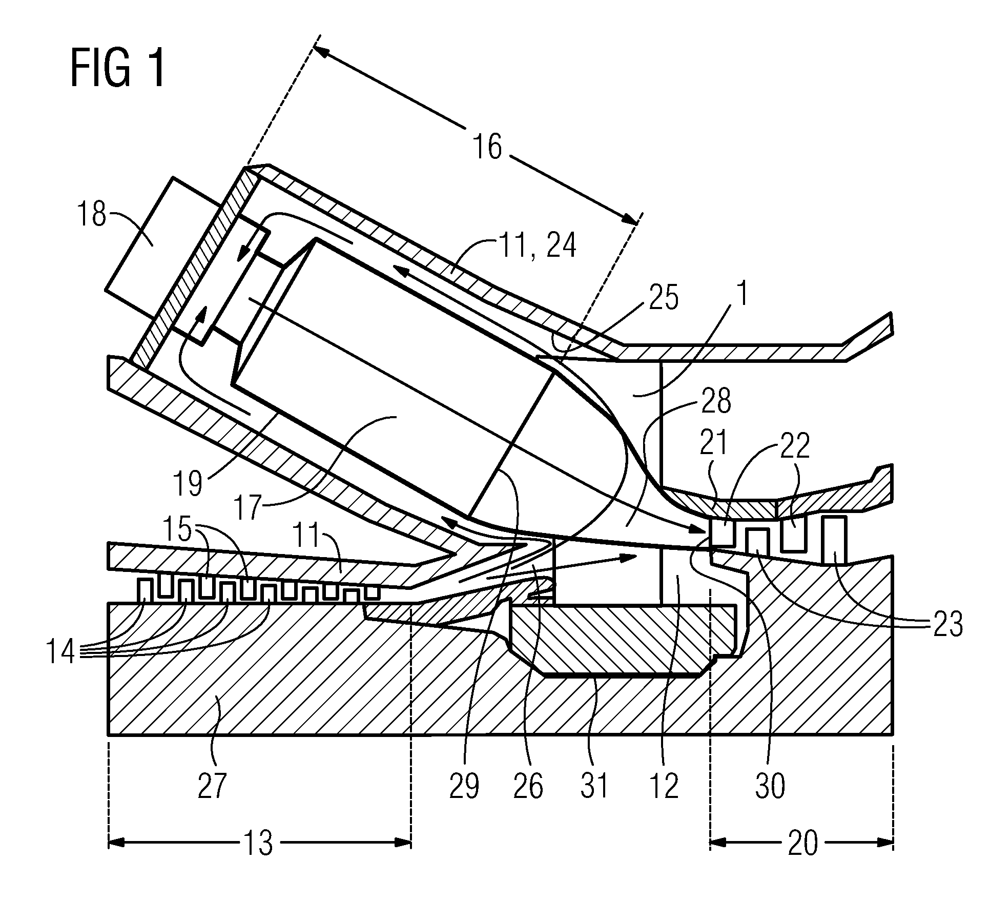
[0031]FIG. 1 shows a schematic view of part of a longitudinal section of an embodiment of a gas turbine engine. The engine comprises a compressor section 13, a combustor section 16 and a turbine section 20 which are arranged adjacent to each other on a longitudinal axis of the engine. A casing 11 surrounds the compressor section 13, the combustor section 16 and the turbine section 20.

[0032]In the compressor section 13, compressor blades 14 and compressor vanes 15 are grouped so as to form blade rings and vane rings, respectively. Blade rings are fixed to and rotating with the shaft 27, forming a rotor assembly. Compressor vane 15 rings are fixed to the casing 11 so as to be stationary with respect to the rotating shaft 27 and compressor blade 14 rings.

[0033]The combustor section 16 comprises one or more combustion chambers 17 and at least one burner 18 fixed to each combustion chamber 17. The combustion chamber 17 is, on one side, in flow connection with the compressor section 13 th...


PUM


Abstract

A section of a gas turbine engine including a radial spoke is provided. The spoke includes an aerodynamic shape with a leading side and a trailing side and, extending from the leading side to the trailing side, a first side and a second side, opposite the first side. The spoke also includes at least one flow guiding element arranged on at least the first side.

Description

CROSS REFERENCE TO RELATED APPLICATIONS[0001]This application is the US National Stage of International Application No. PCT / EP2008 / 050867, filed Jan. 25, 2008 and claims the benefit thereof. The International Application claims the benefits of European application No. 07001910.4 EP filed Jan. 29, 2007, both of the applications are incorporated by reference herein in their entirety.FIELD OF THE INVENTION[0002]The present invention relates to the centre casing of a gas turbine engine.BACKGROUND OF THE INVENTION[0003]Many components of a gas turbine engine must be supported in such a manner that they are retained in an axial direction of the engine and in the circumferential direction of the casing. For this purpose, in the centre casing area of a gas turbine engine outer carrier rings support nozzle guide vanes or stator vanes. A carrier ring itself is supported either by spokes, which also support the bearing and therefore the shaft of the engine and carry oil and buffer or sealing a...

Claims


Application Information

Patent Timeline
Patent Type & Authority Patents(United States)
IPC IPC(8): F02C7/20F03D5/00F03B1/00
CPCF01D9/041F01D25/162F23R3/04F23R3/60F05D2240/127
Inventor MALTSON, JOHN DAVID
Owner SIEMENS AG
Why Eureka
Try Eureka