Tracking object selection apparatus, method, program and circuit

a technology of object selection and selection apparatus, applied in the field of tracking object selection apparatus, method, program and circuit, can solve the problems of difficult selection of such imaging apparatus, and achieve the effect of easy identification, low visibility, and convenient operation

Active Publication Date: 2013-04-30
PANASONIC INTELLECTUAL PROPERTY CORP OF AMERICA
View PDF17 Cites 12 Cited by
  • Summary
  • Abstract
  • Description
  • Claims
  • Application Information

AI Technical Summary

Benefits of technology

[0026]The tracking object selection apparatus according to the present invention allows a user to correctly select an intended object in a picture even when the object is moving (see (A) of FIG. 2) or has a low level of visibility (specifically, a user cannot (easily) identify an object (from a plurality of objects) due to a small size or an inappropriate orientation of the objects) (see (B) of FIG. 2).
[0027]In other words, the apparatus according to the present invention allows a user to perform operations with more ease to a sufficiently high degree, with an image (the “other image” in the present description) securely and appropriately disposed.

Problems solved by technology

However, it is difficult for such imaging apparatuses to select a face to use as a basis for such control when more than one face is detected.

Method used


Image

  • Tracking object selection apparatus, method, program and circuit
  • Tracking object selection apparatus, method, program and circuit
  • Tracking object selection apparatus, method, program and circuit

Examples


embodiment 1

[0069]In Embodiment 1, a tracking object selection apparatus (a tracking object selection apparatus la) is disclosed.

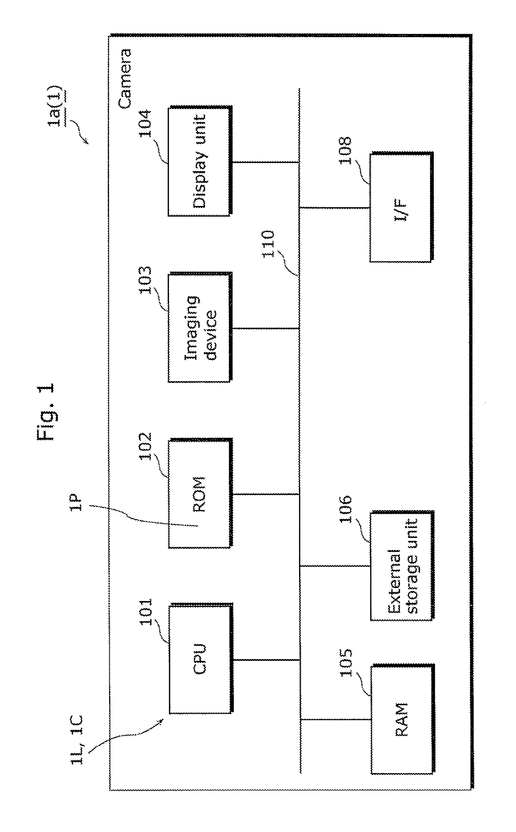
[0070]FIG. 1 shows a block diagram of the tracking object selection apparatus.

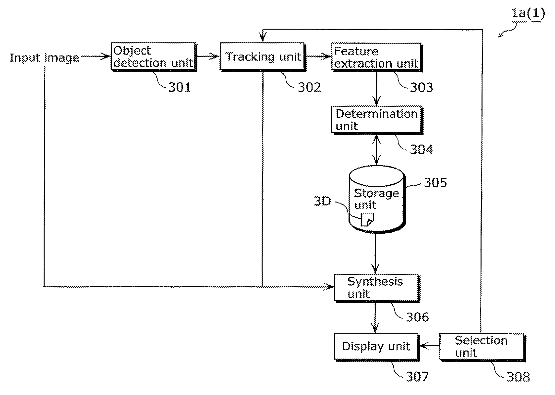
[0071]FIG. 3 shows a functional block diagram of the tracking object selection apparatus according to Embodiment 1.

[0072]The following describes a configuration of the tracking object selection apparatus according to Embodiment 1 with reference to FIG. 1.

[0073]Referring to FIG. 1, a central processing unit (CPU) 101 executes an image processing program (for example, a computer program 1P) for processing according to a flowchart shown in FIG. 4 and FIG. 5 (described later) and controls the components shown in FIG. 3 via a bus 110. The image processing program is stored in a read-only memory (ROM) 102.

[0074]In addition, for example, a random-access memory (RAM) 105 and an external storage unit 106 have an area functioning as a storage unit 305 shown in FIG. 3 and a primary storage area necessa...

embodiment 2

[0144]FIG. 15 is a functional block diagram of a tracking object selection apparatus which uses character information according to Embodiment 2 (an apparatus 1b).

[0145]The apparatus 1b includes an object detection unit 1501, a tracking unit 1502, a feature extraction unit 1503, a character recognition unit 1504, a storage unit 1505, a synthesis unit 1506, a display unit 1507, and a selection unit 1508.

[0146]Operations of these units are detailed later.

[0147]FIG. 16 shows a flowchart up to a display process, illustrating a functional configuration (a process configuration) of the tracking object selection apparatus according to Embodiment 2 of the present invention.

[0148]Embodiment 2 has many features in common with Embodiment 1, and thus the following particularly describes steps performed by the character recognition unit and the following steps (Step S1604 and later) in detail.

[0149]In Step S1604, the feature extraction unit 1503 extracts a feature necessary for character recognit...

embodiment 3

[0161]FIG. 18 is a functional block diagram of a tracking object selection apparatus which uses character information according to Embodiment 3 (an apparatus 1c).

[0162]The apparatus 1c includes an object detection unit 1801, a tracking unit 1802, a feature extraction unit 1803, a similarity calculation unit 1804, a storage unit 1805, a synthesis unit 1806, a display unit 1807, a selection unit 1808, and a registration database (DB) 1809.

[0163]FIG. 19 shows a flowchart up to a display process, illustrating a functional configuration (a process configuration) of the tracking object selection apparatus according to Embodiment 3 of the present invention.

[0164]Embodiment 3 has many features in common with Embodiment 1, and thus the following particularly describes the steps performed by the determination unit and the following steps (Step S1905 and later) in detail.

[0165]In Step S1905, the similarity calculation unit 1804 performs matching between a feature extracted from an image of a c...


PUM


Abstract

A tracking object selection apparatus which selects a tracking object. The tracking object selection apparatus includes a synthesis unit which synthesizes an input image and an image so that the image is disposed at a predetermined position, a display unit, and a selection unit which selects, as the tracking object in a predetermined process, a detected object when an operation is performed on the image displayed at the predetermined position.

Description

TECHNICAL FIELD[0001]The present invention relates to a technique used in areas such as a digital still camera, a digital video camera, a network camera, and a security camera, and used for correct selection of a tracking object in a picture.BACKGROUND ART[0002]In recent years, small-sized electric apparatuses with imaging functions, typified by a digital still camera and a digital video camera, have become popular, and the imaging functions have been made more sophisticated.[0003]For example, these imaging apparatuses usually include a display such as an LCD which allows users to check an image to be recorded on the display and capture an image of the object. At present, in the areas of digital still cameras and digital video cameras, some imaging apparatuses may detect a face of a person and automatically focus on the detected face (autofocus (AF)) or automatically adjust exposure according to the detected face (automatic exposure (AE)), and some may measure a smile on a detected ...

Claims


Application Information

Patent Timeline
Patent Type & Authority Patents(United States)
IPC IPC(8): G06F3/033
CPCG06K9/00248G06T7/20G06K9/00315H04N5/23293H04N5/23216H04N5/23219G06T2207/20104G06T2207/30201G06V40/165G06V40/176H04N23/62H04N23/611
Inventor OGURA, YASUNOBUMONOBE, YUSUKE
Owner PANASONIC INTELLECTUAL PROPERTY CORP OF AMERICA
Why Eureka
Try Eureka