Measuring apparatus and measuring method

a technology of measuring apparatus and measuring method, which is applied in the direction of static indicating device, instruments, editing/combining figures or texts, etc., can solve the problems of difficult smooth adjustment, inability to perform fine adjustment, and inability to smoothly adjust the position of waveform markers, so as to achieve smooth adjustment, smooth adjustment, and easy operation

Active Publication Date: 2013-07-16
ANRITSU CORP
View PDF15 Cites 4 Cited by
  • Summary
  • Abstract
  • Description
  • Claims
  • Application Information

AI Technical Summary

Benefits of technology

Enables smooth and precise adjustment of the waveform marker position and easy separation of peak points, improving operational efficiency and accuracy in measuring apparatuses.

Problems solved by technology

When an operator moves a waveform marker (which is also called a marker, a cursor, and the like) to match the position of a target point on a display screen by manually operating an operating section, for example, a mouse or the like while observing the display screen, there are some difficulties, such as passing the target point, in performing fine adjustment.
For this reason, there was a possibility that positioning of the waveform marker could not be performed smoothly.
Especially when the moving speed was changed to a plurality of steps, there was a disadvantage in that smooth adjustment became further difficult.

Method used


Image

  • Measuring apparatus and measuring method
  • Measuring apparatus and measuring method
  • Measuring apparatus and measuring method

Examples


first embodiment

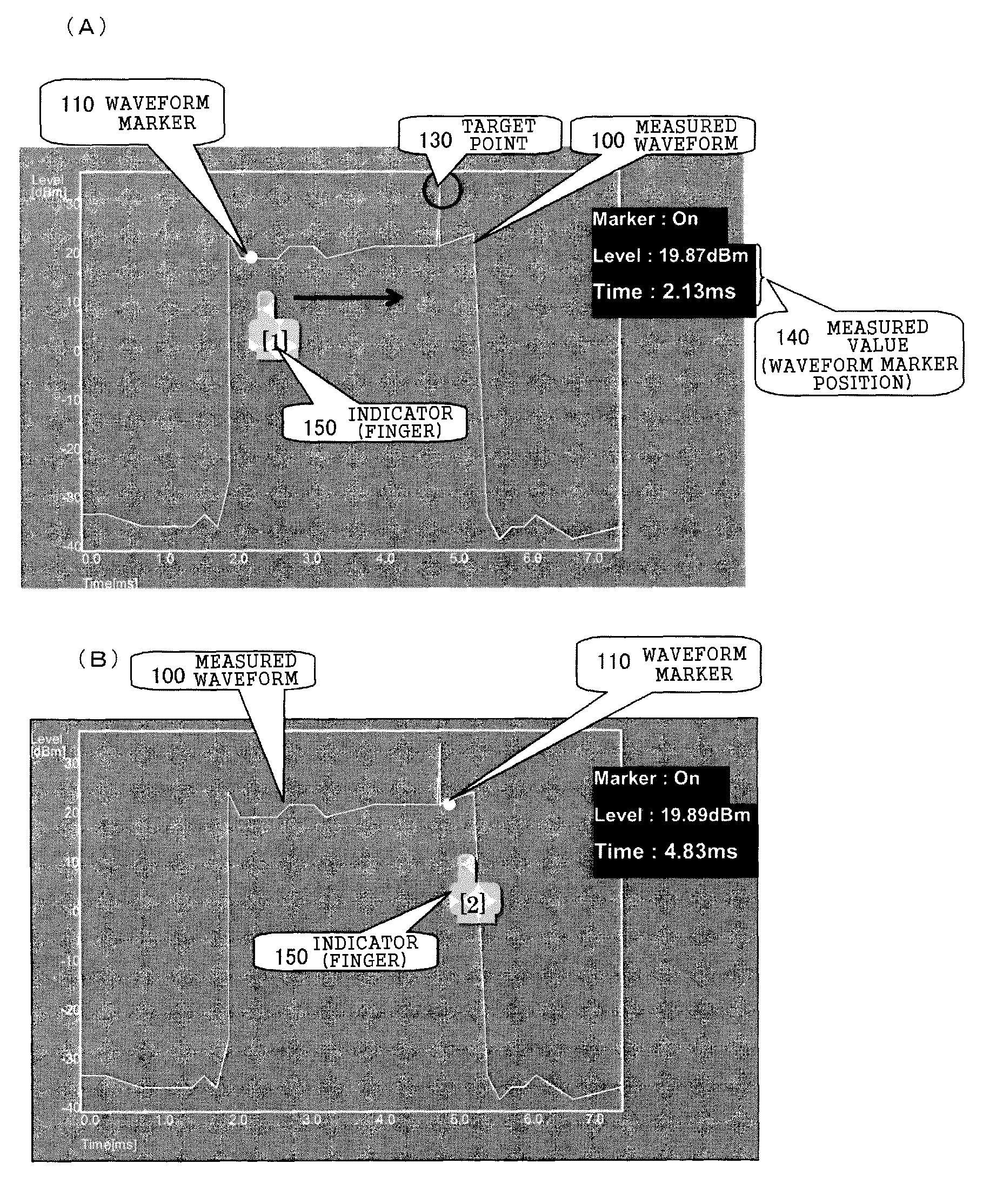
[0088]The first embodiment will be described with reference to FIG. 1. Here, the measuring section 30 checks a tested apparatus, such as a mobile communication apparatus, by transmitting a signal from a signal generating section 30a, which is specified in an actual wireless system, to the tested apparatus and receiving and analyzing the signal from the tested apparatus by a signal analysis section 30b. In this case, the received signal may be analyzed in a time domain or the frequency spectrum of the signal may be analyzed in a frequency domain. When performing such analyses, the received signal or a signal obtained by converting the received signal is transmitted to a display control section 20 as a measured waveform 100 in a time domain, which is displayed in a display section 11 as time domain coordinates having the horizontal axis as a time and the vertical axis as a level (that is, the amplitude of a measured waveform) at the time, or as a measured waveform 100 of the spectrum,...

second embodiment

[0121]While a touch panel is used in the first embodiment shown in FIG. 1, the second embodiment shown in FIG. 9 is the case where a normal display device having no sensor function on a screen is used. In the case of a touch panel, the touch panel itself can sense an operation using an operator's finger or a pen and details of the operation can be visually recognized. In the second embodiment, however, an indicator marker 150a which can be visually recognized on the screen is displayed instead of the operator's finger or the pen and the indicator marker 150a can be moved by an operation from an operating section 42, so that the same function and effects as in the first embodiment can be acquired.

[0122]Hereinafter, an explanation focused on a different point from the first embodiment will be given with reference to FIG. 9. In FIG. 9, the configuration of the same reference numeral as in FIG. 1 has the same function.

[0123]A user I / F section 40 and a display control section 50 shown in...

third embodiment

[0129]In the third embodiment, the measuring apparatus has a function of a zone marker 170 with a variable width and a function of a peak marker 110a, which is displayed at a peak point of the measured waveform 100 within the zone marker 170, instead of the index 120 and the waveform marker 110 in the first embodiment.

[0130]The third embodiment will be described with reference to FIG. 12. In FIG. 12, main components to which the same reference numerals as in FIGS. 1 and 9 are given have the same functions.

[0131]A data display control section 61 in the display control section 60 stores the amplitude (equivalent to the position on the vertical axis) of the measured waveform 100 from the measuring section 30 in a measured data storage section 61a using as an address the time information in a measured time range (equivalent to the position on the horizontal axis) when measured. In addition, the measured waveform 100 stored in the measured data storage section 61a is displayed on a scree...


PUM


Abstract

There is provided a technique for smoothly performing position (movement) adjustment of a waveform marker by making switching between rough adjustment and fine adjustment in a series of marker operations possible with a single means and continuously. A display control section displays a measured waveform on the two-dimensional coordinates, which have a first axis and a second axis perpendicular to the first axis, on the display section. A waveform marker is movable by a marker operation corresponding to a direction parallel to the first axis. The display control section has a detecting section, which detects the marker operation corresponding to a direction parallel to the second axis, and changes either setting of the waveform marker or the display range of the measured waveform according to the detection result of the detecting section.

Description

BACKGROUND OF THE INVENTION[0001]1. Field of the Invention[0002]The present invention relates to a measuring apparatus which measures, for example, an object to be measured or a signal to be measured and displays the measured data. In particular, the invention relates to a measuring apparatus capable of easily setting a waveform marker at a target point by displaying a measured waveform on the basis of measured data and designating the target point on the measured waveform with the waveform marker when calculating the characteristic value of the measured waveform of the specific point, for example.[0003]2. Description of the Related Art[0004]When an operator moves a waveform marker (which is also called a marker, a cursor, and the like) to match the position of a target point on a display screen by manually operating an operating section, for example, a mouse or the like while observing the display screen, there are some difficulties, such as passing the target point, in performing ...

Claims


Application Information

Patent Timeline
Patent Type & AuthorityPatents(United States)
IPC IPC(8): G06T11/20G06T15/10G01R1/02G06T11/60
CPCG01R13/0245G06T11/206G01R1/025G06T11/203G06T11/20G06T11/60
InventorAOKI, KAZUNORI
OwnerANRITSU CORP