Firearm sight with dual diamond shaped apertures

a diamond-shaped aperture and sight technology, applied in the field of sightings for firearms, can solve the problems of low bullet strike rate, complicated process, added factors, etc., and achieve the effect of facilitating rotation of the support member

Active Publication Date: 2014-01-07
TROY STEPHEN P
View PDF14 Cites 3 Cited by
  • Summary
  • Abstract
  • Description
  • Claims
  • Application Information

AI Technical Summary

Problems solved by technology

However, there are added factors complicating this simple process.
A greater distance will result in a low bullet strike.

Method used


Image

  • Firearm sight with dual diamond shaped apertures
  • Firearm sight with dual diamond shaped apertures
  • Firearm sight with dual diamond shaped apertures

Examples


Embodiment Construction

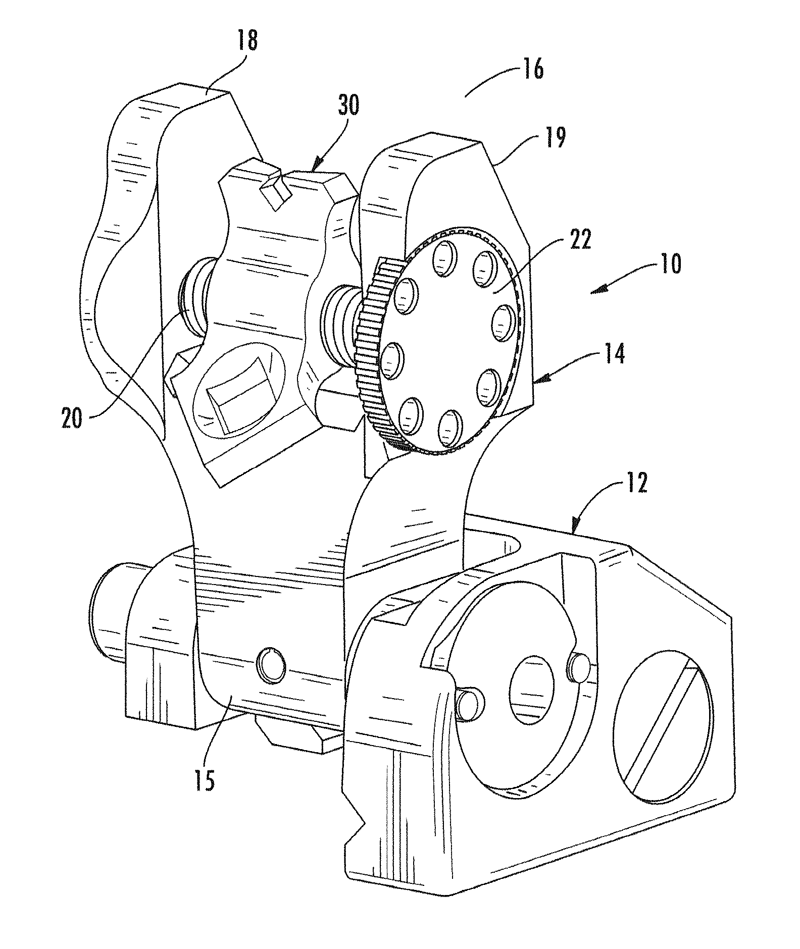
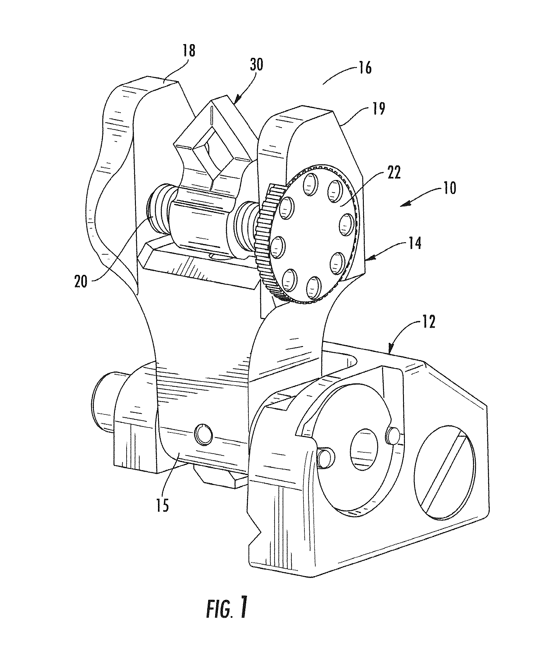
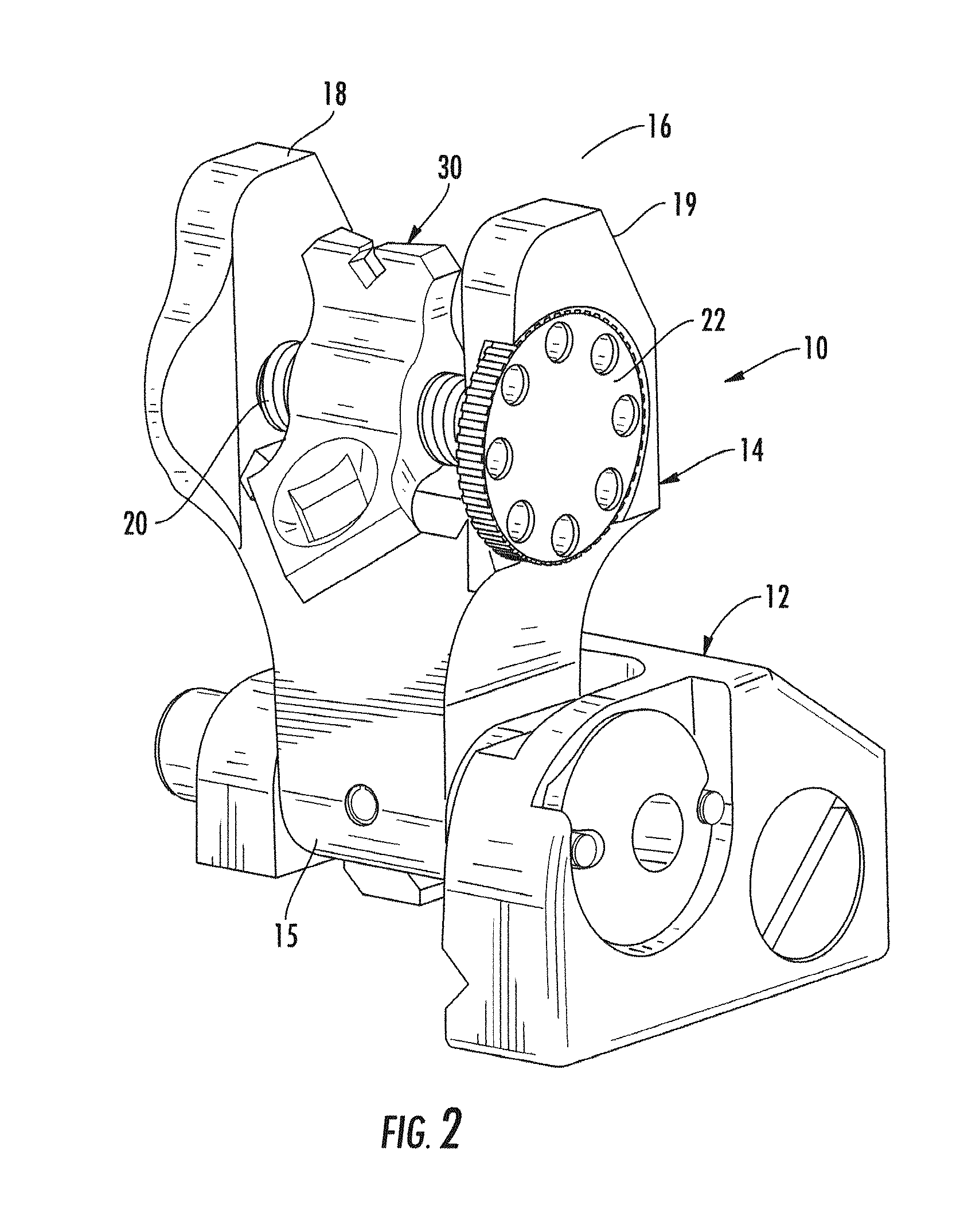
[0014]Turning now to the drawings in which like reference characters indicate corresponding elements throughout the several views, attention is first directed to FIGS. 1 and 2 which illustrates a rear sight for use on a firearm, generally designated 10. Rear sight 10 is couplable to, or proximate, the receiver of a firearm and is used in combination with a front sight. Sight 10, in the present embodiment includes an attachment base 12 configured to be received by and secured to a rail of a firearm. One of ordinary skill in the art will understand that the rail can be attached to or be a part of the receiver of a firearm, or can be a part of or attached to a handguard carried by the firearm. It will also be understood that a fixed or integral base can also be employed.

[0015]A pivoting frame member 14 includes an end 15 pivotally coupled to base 12 and an opposing end 16. Frame member 14 is moveable between an upright position (illustrated) in which sight 10 is configured for use, and...


PUM


Abstract

A sight for use on a firearm includes a frame member mountable to a firearm and having a pair of spaced apart posts extending therefrom, a support member extending transversely between the pair of posts and selectively rotatable with respect thereto, and a sight element. The sight element is carried by the support member between the posts and includes a central portion rotatably coupled to the support member, a first sight aperture portion extending from the central portion and defining a first aperture formed in a diamond shape with an upper v-notch and a lower v-notch, and a second sight aperture portion extending from the central portion and defining a second aperture formed in a diamond shape.

Description

CROSS-REFERENCE TO RELATED APPLICATION[0001]This application claims the benefit of U.S. Provisional Application No. 61 / 351,456, filed 4 Jun. 2010.FIELD OF THE INVENTION[0002]This invention relates to firearm accessories.[0003]More particularly, the present invention relates to sights for firearms.BACKGROUND OF THE INVENTION[0004]In the field of firearms, sights are numerous and varied but are used for a single purpose. A sight system is intended to put a bullet on a target. Sight systems include, in a basic form, a rear sight and a front sight. Lining up the front sight with the rear sight is intended to determine the striking position of the bullet. However, there are added factors complicating this simple process. The distance the bullet must travel will cause a deviation from the designated target. In other words, a front and rear sight can be adjusted to deliver bullet on target at a specific distance. A greater distance will result in a low bullet strike. This deviation can be ...

Claims


Application Information

Patent Timeline
Patent Type & Authority Patents(United States)
IPC IPC(8): F41G1/10
CPCF41G1/17F41G1/10F41G1/16F41G1/08F41G1/00
Inventor TROY, STEPHEN, P.
Owner TROY STEPHEN P
Why Eureka
Try Eureka