Solid-liquid separating device, filtering apparatus, and solid-liquid separating method

a technology of solid-liquid separation and filtering device, which is applied in the direction of filtration separation, moving filter element filter, separation process, etc., can solve the problems of large differential pressure than the atmospheric pressure, difficult to achieve the liquid content of filtered cake target value, etc., to achieve effective separation of liquid components, reduce liquid content, and squeeze

Active Publication Date: 2014-03-04
TSUKISHIMA KIKAI CO LTD
View PDF34 Cites 0 Cited by
  • Summary
  • Abstract
  • Description
  • Claims
  • Application Information

AI Technical Summary

Benefits of technology

[0039]As described above, according to the solid-liquid separating device and the solid-liquid separating method of the present invention, the material is sandwiched between the pair of separating filter cloths wound around the rotating separating roll so as to overlap each other. Thereby, the material can be effectively squeezed by making a shearing force in the circumferential direction act thereon, in addition to the pressing force in the radial direction of the separating roll. Moreover, it becomes possible to perform ventilation in this radial direction to effectively separate the liquid component. Additionally, according to the filtering apparatus of the present invention, the material with lower liquid content can be obtained efficiently and economically using such a solid-liquid separating device, without requiring a secondary dehydrator. Additionally, when a product is conveyed to such a drying device at the subsequent stage, it is possible to solve conveyance troubles resulting from adhesion to a conveyor, such as a belt conveyor or a screw conveyor.
[0010]As such, in the solid-liquid separating device and the solid-liquid separating method of the above configuration, a material is supplied to and sandwiched between the pair of separating filter cloths, and is wound around and pressed against an outer circumference of the separating roll which rotates in a circumferential direction, whereby the material is squeezed. Consequently, the material which has been supplied can be reliably dehydrated even when the rotation of the separating roll or the traveling of the separating filter cloth along the rotational direction is not only intermittent but also continuous.
[0041]According to the filtering apparatus of the present invention, the material with lower liquid content can be obtained efficiently and economically using such a solid-liquid separating device, without requiring a secondary dehydrator. Additionally, when a product is conveyed to such a drying device at the subsequent stage, it is possible to solve conveyance troubles resulting from adhesion to a conveyor, such as a belt conveyor or a screw conveyor. Additionally, a decrease in the frictional force between the separating roll and the separating filter cloths by ventilation can be suppressed, and the separating filter cloths can be reliably made to travel integrally in the rotational direction of the separating roll by the squeezing belt. Thus, even if the separating roll is used as a drive roll of a filtering apparatus, such as a horizontal vacuum filtering apparatus, and the separating filter cloths are used as filtering device of this filtering apparatus, stable traveling of the filter cloths can be achieved.

Problems solved by technology

However, a larger differential pressure than the atmospheric pressure cannot be acted under normal circumstances.
Consequently, it is difficult for the liquid content in a filtered cake to achieve a target value, and a secondary dehydrator, such as a centrifuge or a filter press, should often be required to additionally prepare at a subsequent stage of this filtering apparatus.

Method used


Image

  • Solid-liquid separating device, filtering apparatus, and solid-liquid separating method
  • Solid-liquid separating device, filtering apparatus, and solid-liquid separating method
  • Solid-liquid separating device, filtering apparatus, and solid-liquid separating method

Examples


first embodiment

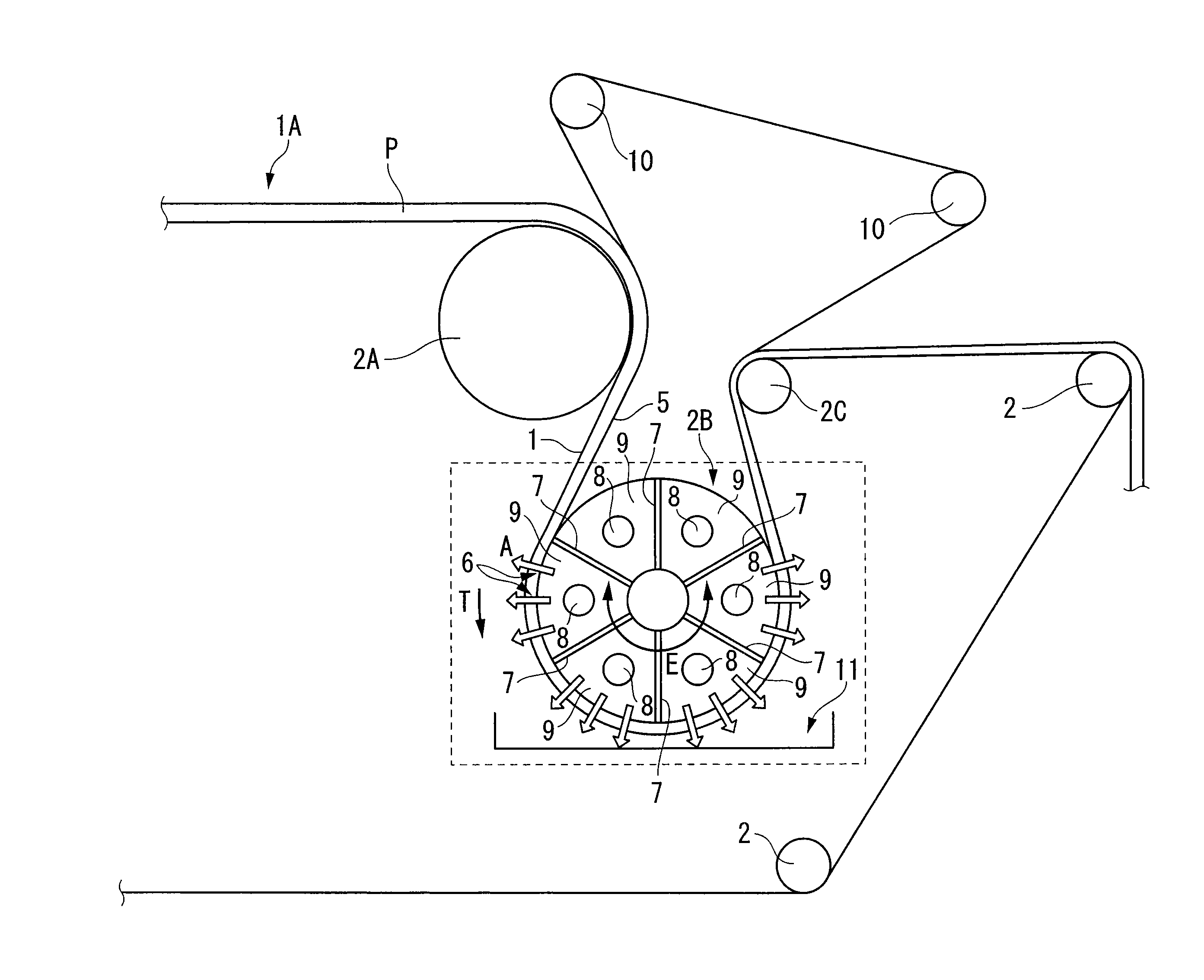
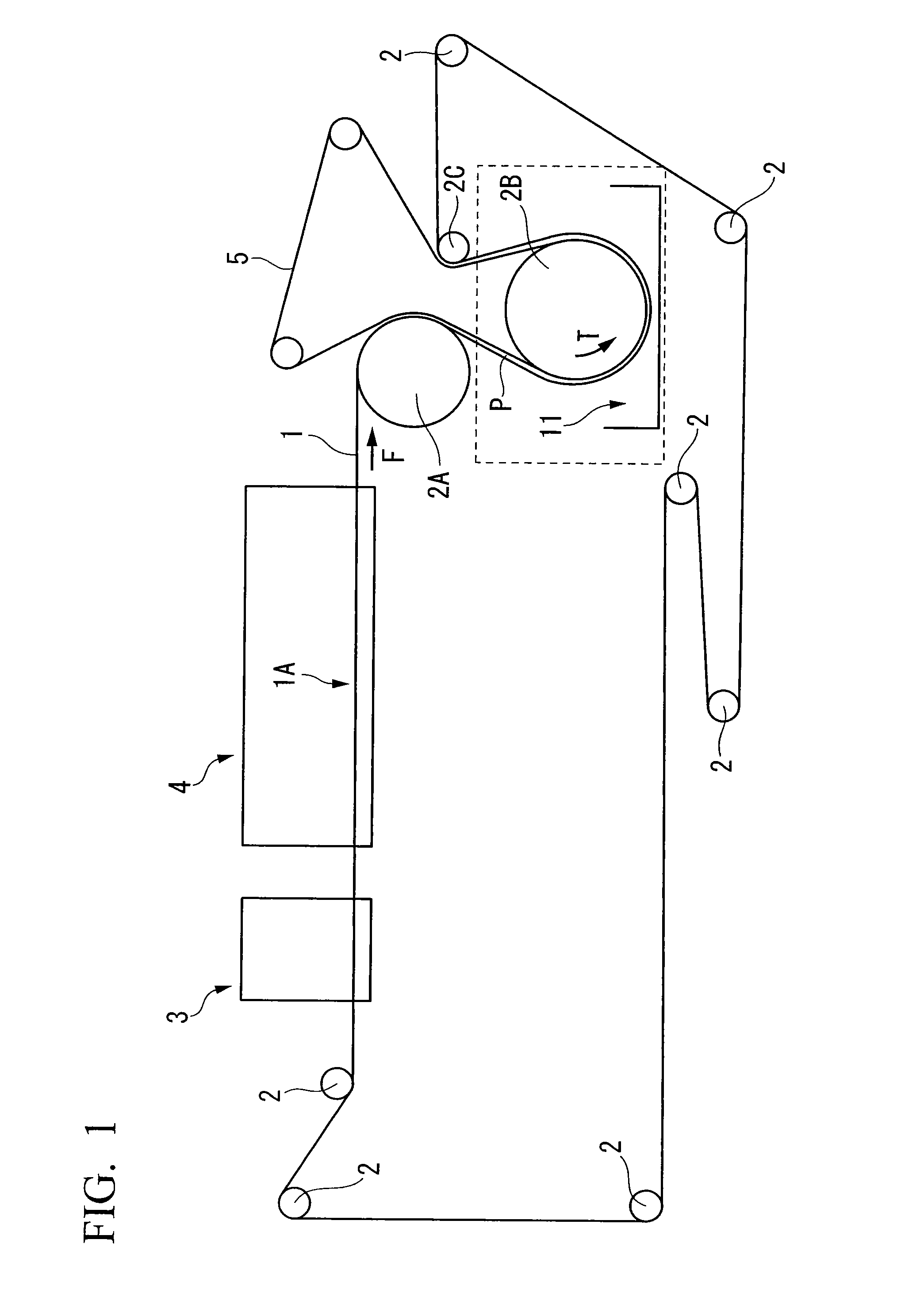
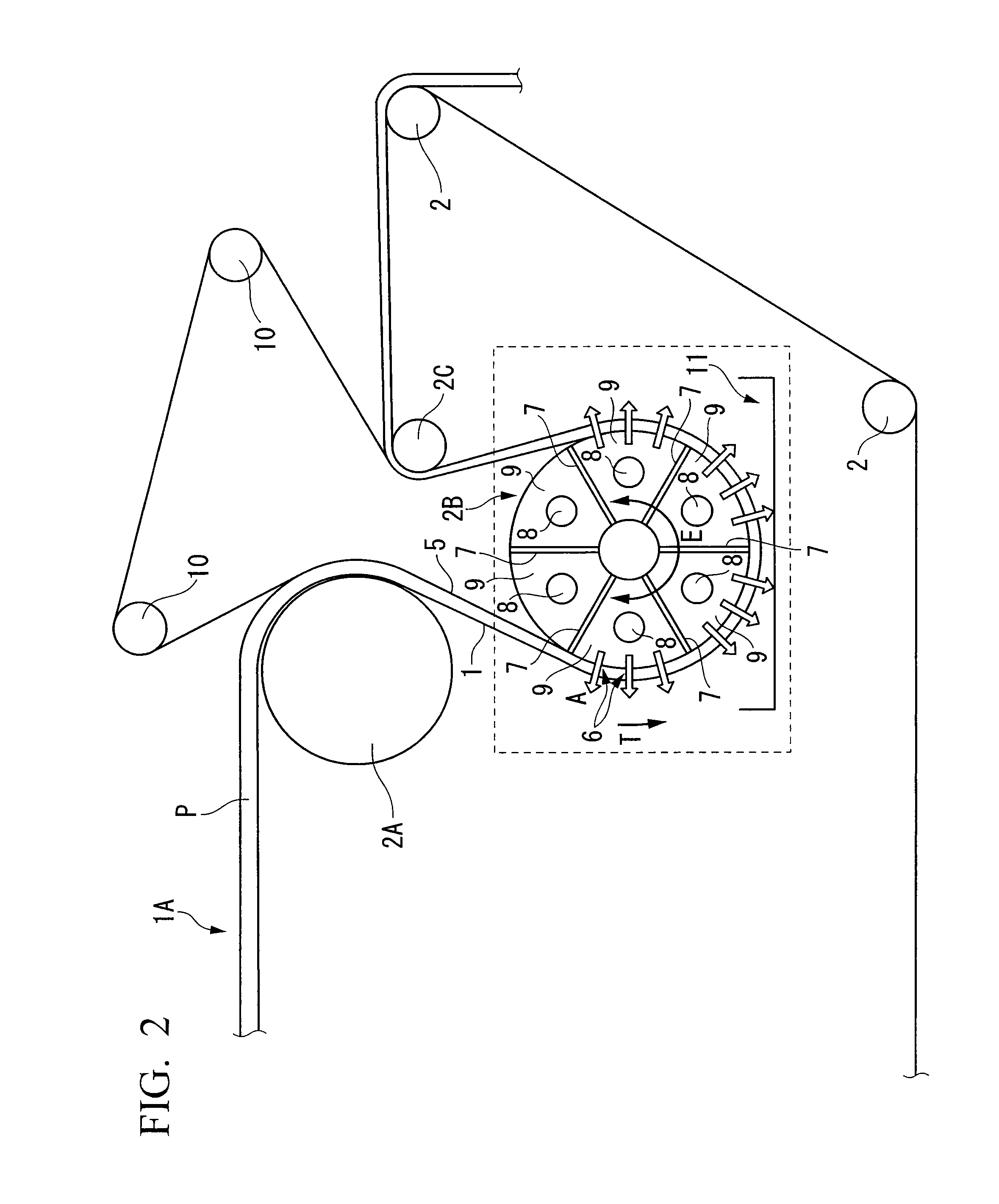
[0054]FIGS. 1 to 6 show a solid-liquid separating device and a filtering apparatus including the solid-liquid separating device of the present invention. The filtering apparatus in this embodiment is the configuration of a horizontal vacuum filtering apparatus. As shown in FIG. 1, a filter cloth 1 which is endless is wound around a plurality of rolls 2 which are arranged parallel to each other with their axes being made horizontal, and is stretched horizontally so as to go therearound. As one of these rolls is used as a drive roll 2A and is rotationally driven around its axis, a horizontal portion 1A of the filter cloth 1 which is stretched at an upper portion of the apparatus is able to travel so as to move in a traveling direction indicated by an arrow F. A material P supplied from a supply device 3 disposed behind the horizontal portion 1A in the traveling direction F is filtered via the filter cloth 1 by a filtering device 4 disposed between the supply device 3 and the drive rol...

second embodiment

[0086]FIGS. 8 to 10 show a solid-liquid separating device and a filtering apparatus including the solid-liquid separating device of the present invention. The filtering apparatus in this embodiment is the configuration of a horizontal vacuum filtering apparatus. As shown in FIG. 8, an endless filter cloth 101 is wound around a plurality of rolls 102 which are arranged parallel to each other with their axes being made horizontal, and is stretched horizontally so as to go therearound. As one of these rolls is used as a drive roll 102A and is rotationally driven around its axis, a horizontal portion 101A of the filter cloth 101 which is stretched at an upper portion of the apparatus is able to travel so as to move in a traveling direction indicated by an arrow F. A material P supplied from a supply device 103 disposed behind the horizontal portion 101A in the traveling direction F is filtered via the filter cloth 101 by a filtering device 104 disposed between the supply device 103 and ...


PUM

PropertyMeasurementUnit
particle sizeaaaaaaaaaa
diameteraaaaaaaaaa
diameteraaaaaaaaaa

Abstract

A solid-liquid separating apparatus is provided with: a separating roll which has a substantially cylindrical shape with a plurality of through holes, which penetrate between an inner surface and an outer surface in radial direction thereof, and is rotatable in circumferential direction thereof; and a pair of separating filter cloths which is endless belts capable of traveling in a rotation direction of the separating roll and are wound around the outer circumference of the separating roll so as to overlap each other, wherein a material supplied between the pair of filter cloths is squeezed by being rolled together with the pair of filter cloths therebetween on the outer circumference of the separating roll, and the material is dehydrated by ventilating via each through hole.

Description

TECHNICAL FIELD[0001]The present invention relates to a solid-liquid separating device used particularly as a secondary dehydration mechanism of a horizontal vacuum filtering apparatus, a drum type vacuum filtering apparatus, and a filtering apparatus like a beltpress dehydrator of only a machine squeezing dehydration mechanism which filter a material supplied onto a filter cloth which is wound around a plurality of rolls and travels therealong, a filtering apparatus using the solid-liquid separating device, and a solid-liquid separating method.[0002]Priority is claimed on Japanese Patent Application No. 2008-078286, Japanese Patent Application No. 2008-266484, and Japanese Patent Application No. 2008-278408, the contents of which are incorporated herein by reference.DESCRIPTION OF RELATED ART[0003]Among such filtering apparatuses, the horizontal vacuum filtering apparatus generally supplies a material onto a filter cloth which travels on a vacuum tray continuously or intermittently...

Claims


Application Information

Patent Timeline
Patent Type & Authority Patents(United States)
IPC IPC(8): B01D33/04
CPCB01D33/042B01D36/02B30B9/246
Inventor HOMMA, TOMOKIHIGAMI, TAKASHIIWASAKI, SHUJITACHIKAWA, TOSHIAKISAKURAI, NOBUTAKA
Owner TSUKISHIMA KIKAI CO LTD
Why Eureka
Try Eureka