Bottle and cap

a technology for bottles and caps, applied in the field of bottles and caps, can solve the problem that the bottle cap cannot be removed from the bottle, and achieve the effect of minimizing air permeability and minimizing surface tension

Inactive Publication Date: 2014-03-18
CAP CRAFT CORP
View PDF61 Cites 17 Cited by
  • Summary
  • Abstract
  • Description
  • Claims
  • Application Information

AI Technical Summary

Benefits of technology

[0005]The bottle cap, payload cap and bottle cooperate to define two compartments—one compartment within the bottle and another within the cap. Specifically, the payload cap includes a cylindrical chamber that cooperates with the bottle cap to form a payload cavity in which liquid or other material can be contained separate from the contents of the bottle. The payload cap and bottle cap are in threaded engagement. Manipulation of the payload cap causes the compartments to communicate allowing the liquid or other material in the compartments to be mixed. The bottle cap has supports and a payload cavity closure. The supports may be biased against the payload cap to prevent the contents of the payload cavity from being inadvertently released into the bottle (for example due to atmospheric temperature and pressure fluctuation).
[0006]Liquid or other material may be stored in the compartment within the cap to protect it from deterioration, e.g. by sunlight, or contamination, until the cap is manipulated to mix the liquids or materials in the compartments. The payload cavity can be used to maintain the potency of any material contained therein.
[0007]The cap has multiple seals to permit sealing of the bottle and payload cavity and discharge of the liquid or other material in the payload cavity into the bottle. There are seals that prevent liquid or other material from escaping / entering from / into the payload cavity. There are seals to prevent liquid or other material from escaping / entering from / into the bottle. The seals are designed such that the contents of the payload cavity can be maintained under positive pressure over atmospheric pressure, the contents of the bottle can be maintained under a negative (vacuum) pressure compared to atmospheric pressure, and the contents of the payload cavity can be mixed with the contents of the bottle without any leakage outside of the bottle or cap.
[0008]The payload cap has tamper-evidence attachments to the bottle cap, and the bottle cap has tamper resistant attachment to the bottle. The bottle cap is in threaded engagement within the bottle. Once screwed to the bottle, the bottle cap cannot be removed from the bottle without physical destroying the bottle cap. The payload cap and bottle cap are not reusable, thus guarding against tampering or misuse of the payload cap, bottle cap and the bottle in any combination.
[0012]Materials used for the construction of the payload cap and bottle cap minimizes air permeability into the payload cavity and protects the material in the payload cavity from the influence of Ultra Violet light. Further, the materials are optimized to have minimum surface tension, so as not to attract the payload after the contents of the payload cavity are discharged into the bottle. The material of construction is plastic alloy based on polyethylene containing other additives (i.e. UV blocker, surface tension reducing additive, and color).

Problems solved by technology

However, these bottles suffer from significant drawbacks such as presenting challenges to sterilization during manufacturing, maintaining the proper sealing of the bottle during use, dispensing of the material from one compartment into the other compartment and providing a tamper-resistant closure.
Once screwed to the bottle, the bottle cap cannot be removed from the bottle without physical destroying the bottle cap.

Method used


Image

  • Bottle and cap
  • Bottle and cap
  • Bottle and cap

Examples


Embodiment Construction

[0018]The foregoing and other features and advantages of the bottle and cap will be apparent from the following, more particular description of a preferred embodiment, as illustrated in the accompanying drawings wherein like reference numbers generally indicate identical, functionally similar, and / or structurally similar elements. While specific exemplary embodiments are discussed, it should be understood that this is done for illustrative purposes only. A person skilled in the relevant art will recognize that other components and configurations can be used without departing from the scope of the invention as defined by the claims.

[0019]Structure of Embodiment of Cap

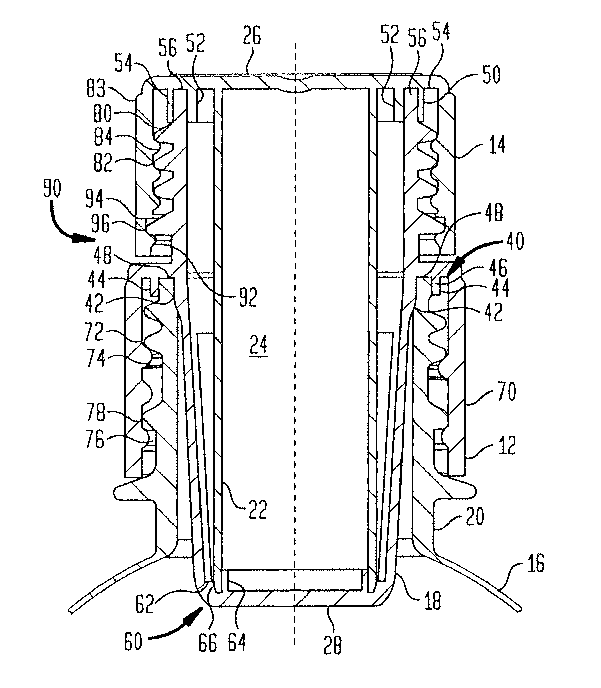
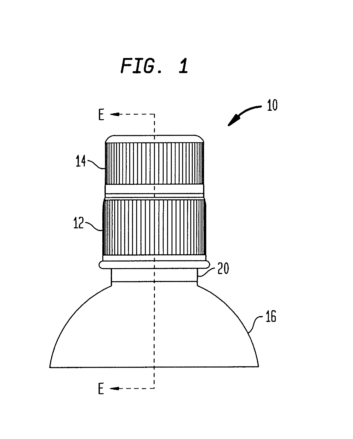
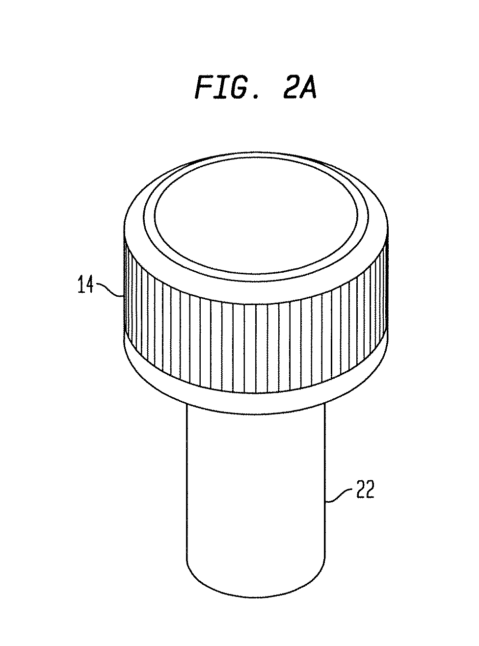
[0020]The cap 10 is comprised of two pieces, a bottle cap 12 and a payload cap 14.

[0021]Bottle cap 12 contacts bottle 16. It has a lower portion 18 that fits within the inner circumference of the neck 20 of the bottle 16 on which cap 10 is used. The payload cap 14 has a lower cylindrical portion 22. The lower cylindrical...


PUM


Abstract

The embodiments described herein disclose a bottle and cap. The cap seals the bottle and thereby defines a compartment within the bottle for storing liquid or other material. The cap also includes an internal compartment for storing a liquid or other material in a sealed manner. The cap is designed to readily allow for sterilization during manufacturing, maintaining proper sealing of the compartments, dispensing material from one compartment into the other and providing a tamper-resistant closure.

Description

FIELD AND BACKGROUND[0001]The present invention relates generally to a bottle and cap defining separate compartments for containing liquids or other materials. Manipulation of the cap allows the compartments to communicate so that the liquid or other materials can be mixed.DESCRIPTION OF THE PRIOR ART[0002]Most bottles in the market today have one compartment for storing a liquid or other material. Some bottles have separate compartments for containing liquids or other materials. U.S. Pat. Nos. 6,170,654, 6,209,718 and 6,644,471 and U.S. Patent Application Publication Nos. 2007 / 0074979 and 2007 / 0193893 are representative of such bottles. However, these bottles suffer from significant drawbacks such as presenting challenges to sterilization during manufacturing, maintaining the proper sealing of the bottle during use, dispensing of the material from one compartment into the other compartment and providing a tamper-resistant closure.SUMMARY[0003]The embodiments described herein disclo...

Claims


Application Information

Patent Timeline
Patent Type & Authority Patents(United States)
IPC IPC(8): B65D51/28
CPCB65D51/28B65D51/18B65D51/2892
Inventor MARTINOVIC, ANDREJZAKKA, RICHARD J.
Owner CAP CRAFT CORP
Why Eureka
Try Eureka