

Coil spring
a coil spring and coil spring technology, applied in the field of coil springs, can solve the problems of preventing achieve the effects of improving the uneven distribution of stress, reducing oblateness, and shortening the close contact length
- Summary
- Abstract
- Description
- Claims
- Application Information
AI Technical Summary
Benefits of technology
Problems solved by technology
Method used
Image

Examples
embodiment 1
Effect of Embodiment 1
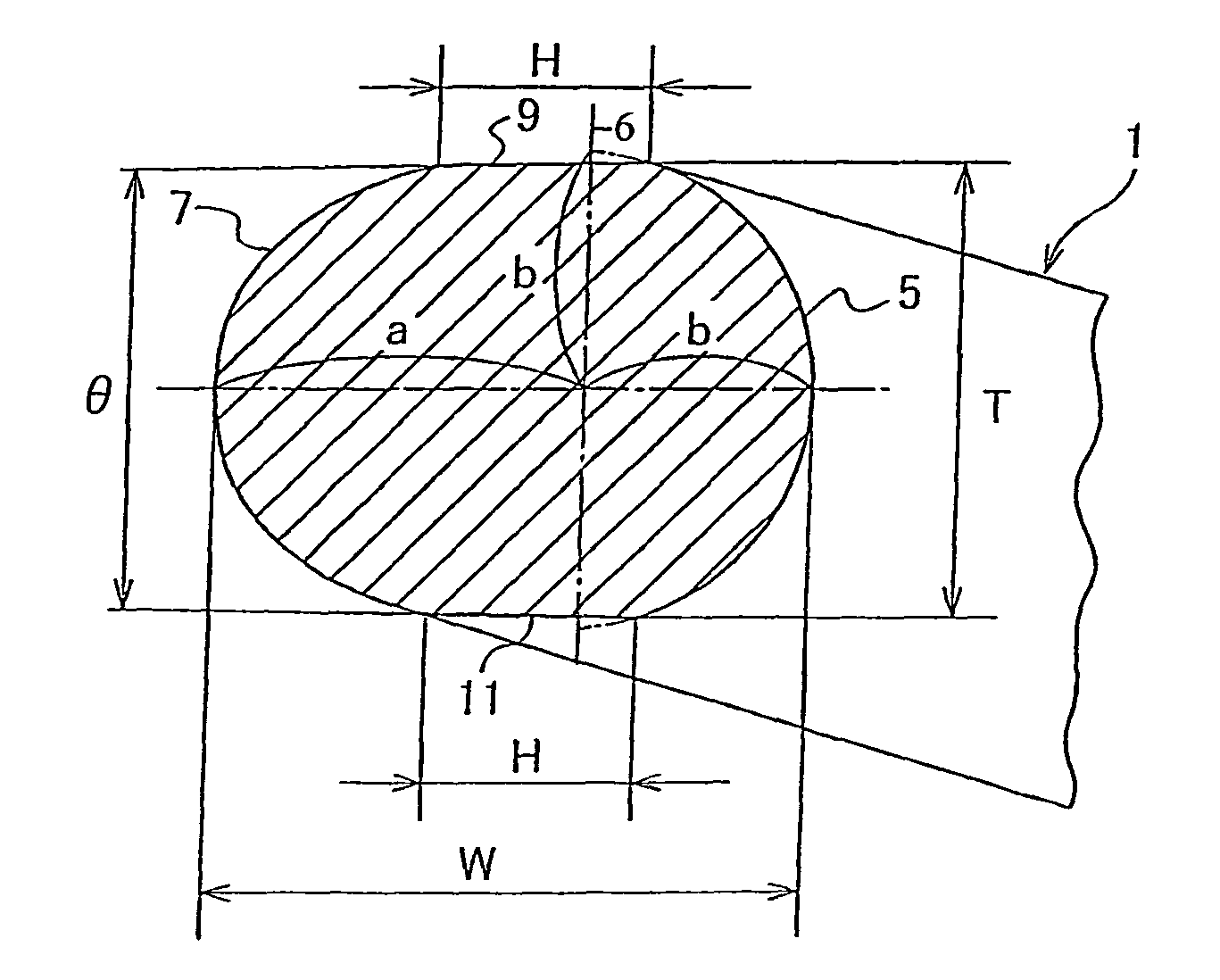
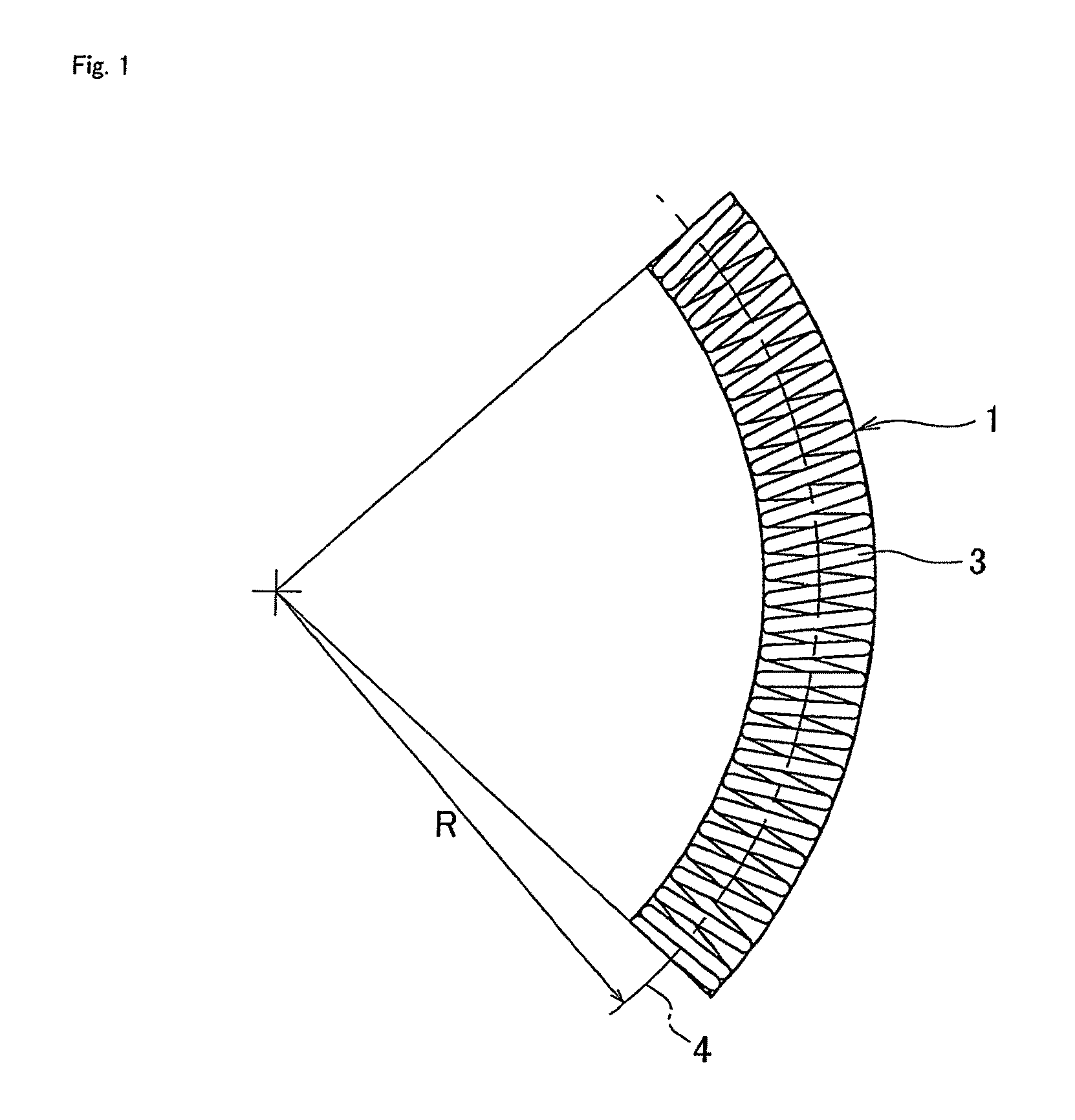
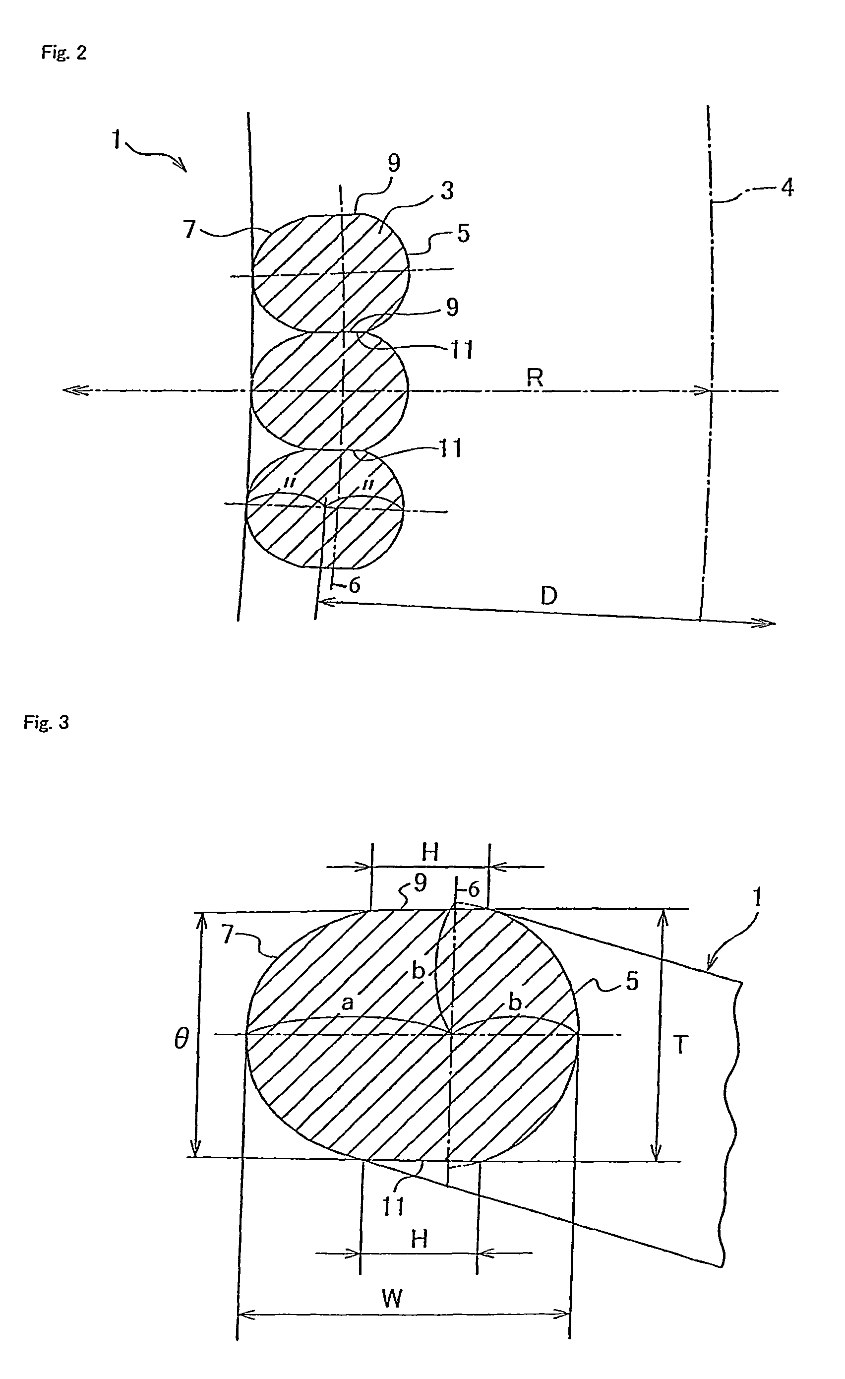
[0055]According to the embodiment of the present invention, the coil spring 1 comprises the spring wire 3 wound in a coil shape having the inner diameter side portion 5 and outer diameter side portion 7 in the cross section. One of the outer diameter side portion 7 or inner diameter side portion 5 is formed in the semi-circular shape expressed by x2+y2=b2, and the other thereof is formed in the non-circular shape with a long diameter “α” and a short diameter “b” expressed by (x / a)α+(y / b)α=1. The value of the “α” is set in a range of 1.85 to 2.45. The coil spring 1 further includes flat faces 9 and 11 provided between the inner diameter side portion 5 and the outer diameter side portion 7 on the peripheral shape of the spring wire in the cross section such that each flat face of each coil comes into contact with a flat face 9 or 11 of an adjacent coil in the axial direction along the axis line 4 of the coil spring 1. Therefore, continuity of stress dispersion in...
PUM
 Abstract
Description
Claims
Application Information