Apparatus for recovering oil from a body of water

a technology for recovering oil and water bodies, applied in water cleaning, separation processes, filtration separation, etc., can solve the problems of low oil recovery rate and oil recovery efficiency, high cost, and high cost of oil spill skimming devices, etc., to achieve the effect of increasing the number of machines, increasing the speed and efficiency, and saving costs

Inactive Publication Date: 2014-06-24
MARTIN SKY BLEU
View PDF6 Cites 2 Cited by
  • Summary
  • Abstract
  • Description
  • Claims
  • Application Information

AI Technical Summary

Benefits of technology

[0006]The present invention uses inexpensive and easy-to-use conveying techniques and an inexpensive separation material to meet objectives. The whole process can be done manually using simple machines and when large volumes are involved, greater speed and efficiency can be accomplished by automating steps and using more complex machines.
[0008]The present invention presents a simple six step method and machine for recovering and separating the primary products of clean water and clean air and the secondary products of oil and other floating contaminants from a composite mixture of these primary and secondary products at the surface of a body of water.
[0010]The second method step is conveying a MRSC (held in the open fillport position) through and along the surface or other location of the composite mixture and collecting the composite mixture in the MRSC. The primary products (clean air and clean water) start flowing out of the sides and bottom of the MRSC almost immediately and passively from compression of material inside the MRSC. The MRSC material is very lightweight and while collecting floating secondary products, it is easy to pull and navigate through the composite mixture while retaining the floating secondary products (oil and other contaminants). This step can be accomplished most efficiently by using a booming device such as the Enviro Boom® (Enviro Boom® is a registered trademark of Skyler Enterprises) to collect the composite mixture into a small area to maximize the depth of the composite mixture in a local area in front and / or off to the side of the invention where the depth of the composite mixture can be controlled at levels of composite mixture depths of at least 1″ for high efficiency or a less composite mixture depth for lower efficiency. The machine for this conveying step can be the same machine used in the first step or may be a machine specifically suited for water use. This step is not limited to applications where the MRSC is pulled through a surface composite mixture at the surface of the water but also can be used applications where the MRSC is dragged through a composite mixture underwater such as an oil plume.
[0014]The six method step is an active or passive step to accomplish further removal of primary product. MRSC in a lay-down area will passively continue to remove primary product naturally through gravity and compression of MRSC contents from the height of an individual MRSC and any additional MRSC that are stored on top of each other. Supplemental removal devices such as a scraper or roller can be used to speed up the process of primary product removal or to remove material from the outside of the MRSC. Filled MRSC containing almost exclusively secondary product can be transported away or can be temporarily returned to the water for later pickup.
[0015]Filled MRSC can be scraped while they are being conveyed away from the water to remove composite mixture from the outside of the MRSC or compressed by rollers to remove primary products from the inside or outside of the MRSC while it is being conveyed. Additional large fillport MRSC may be stationed beneath the conveying zones to catch incidental loss of material from the MRSC or the conveying equipment to prevent return of this material to the clean water.

Problems solved by technology

Oil spills have a disastrous effect on water quality, marine life, and on land areas in the vicinity of a spill.
Many oil spill skimming devices use very expensive conveying and separation techniques that are slow, very costly, difficult-to-use, environmentally unfriendly and have low oil recovery rates and oil recovery efficiencies.

Method used


Image

  • Apparatus for recovering oil from a body of water
  • Apparatus for recovering oil from a body of water
  • Apparatus for recovering oil from a body of water

Examples


Embodiment Construction

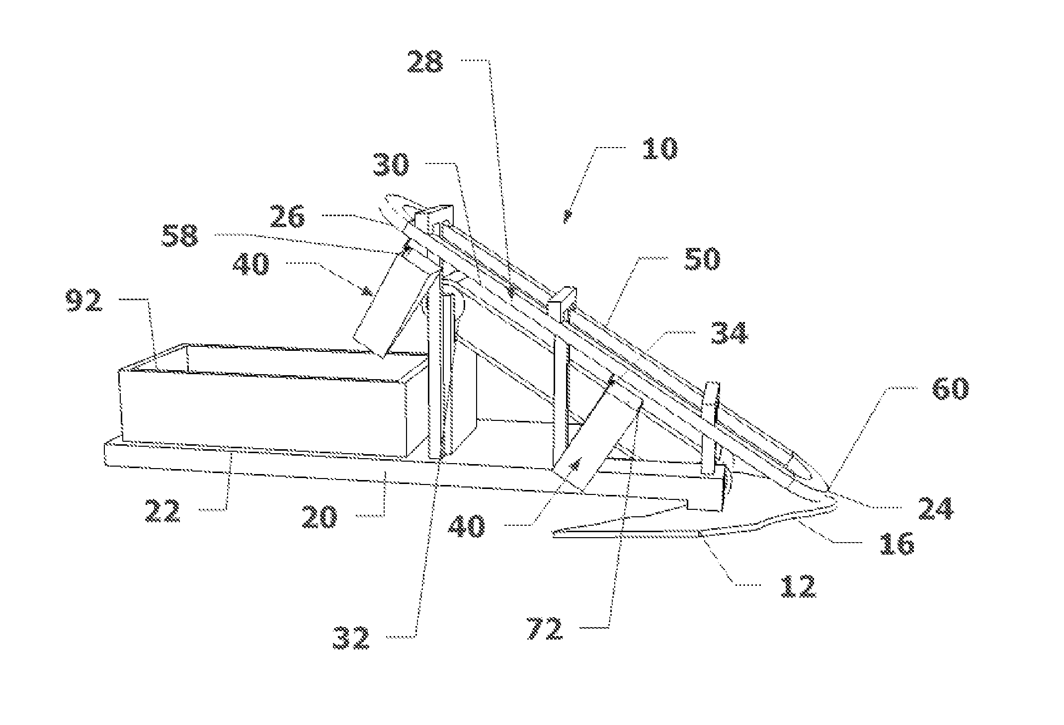
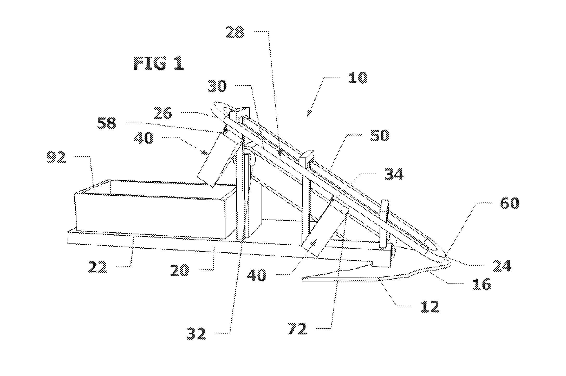
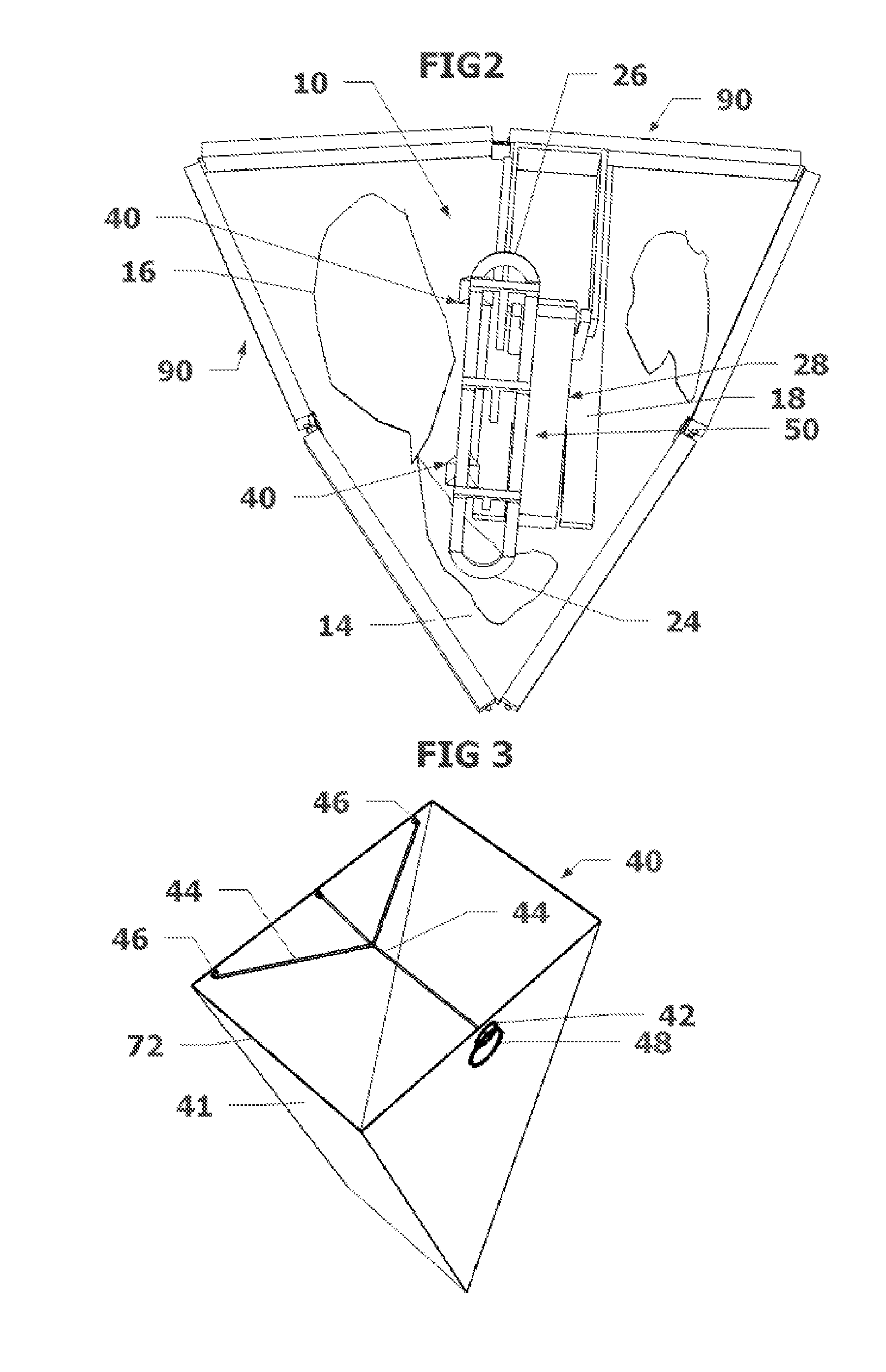
[0022]An apparatus 10 for recovering and separating the primary products of clean water and clean air and the secondary products of oil and other floating contaminants from a composite mixture 16 of these primary and secondary products at the surface 12 of a body of water; comprising a platform base 20 to support the apparatus 10 and provide a lay-down area 22; an inclined plane conveying assembly 28; a vertical support and conveying assembly 50; and a material recovery and holding tank 92 on lay-down area 22. Options include rollers to compress filled Material Recovery and Separation Containers (MRSC) 40 to speed removal of primary product; motorized inclined plane belts 32; motorized inclined plane belts with absorbents 34; fluid extraction devices such as scrapers and rollers to extract secondary product from the absorbent belt 34; platforms 20 that are mounted on a ship or boat; platforms 20 that are mounted on a dock; platforms 20 mounted on a shoreline with extended inclined p...


PUM

PropertyMeasurementUnit
permeableaaaaaaaaaa
areaaaaaaaaaaa
depthaaaaaaaaaa

Abstract

An apparatus to convey and seal a material recovery and separation container (MRSC) that is water and air permeable for in-place material recovery and separation of a primary product of clean water and clean air and a secondary product of floating contaminants such as an oil spill or other pollution from a composite mixture of products at the surface of water or at depths (oil plume). The apparatus has a horizontal platform base for support and to provide a lay-down area, provide an operator support area, and provide a structure for connecting to a local containment boom and standoff. One embodiment is a hook and rail conveying system brings the MRSC to the composite mixture, through the composite mixture for collection, to a container closing area and to a lay-down area. The MRSC is closed after filling.

Description

CROSS-REFERENCE TO RELATED APPLICATIONS[0001]This application claims the benefit of provisional application 61,447,318 titled “In-Place Material Recovery and Separation Apparatus” filed on Feb. 28, 2011 which is incorporated by reference in its entirety. Related subject matter is disclosed in my U.S. patent application Ser. No. 12 / 137,182 filed Jun. 11, 2008 (now abandoned) and Ser. No. 13 / 007,767 filed Jan. 17, 2011 (which is a continuation-in-part of Ser. No. 12 / 137,182) and PCT / US09 / 45099 filed May 23, 2009, now abandoned.STATEMENT REGARDING FEDERALLY SPONSORED RESEARCH OR DEVELOPMENT[0002]Not ApplicableREFERENCE TO SEQUENCE LISTING, A TABLE, OR A COMPUTER PROGRAM LISTING COMPACT DISC APPENDIX[0003]Not ApplicableBACKGROUND OF THE INVENTION[0004]The present invention relates to an In-Place Material Recovery and Separation Apparatus and Method of Use for recovering clean water and clean air from a floating composite mixture of oil and other floating contaminants. The recovery and s...

Claims


Application Information

Patent Timeline
Patent Type & Authority Patents(United States)
IPC IPC(8): E02B15/10C02F1/40E02B15/04
CPCC02F1/40Y10S210/924E02B15/045E02B15/104Y02A20/204
Inventor MARTIN, SKY, BLEU
Owner MARTIN SKY BLEU
Why Eureka
Try Eureka