Optical system

a technology of optical system and optical axis, applied in the field of optical system, can solve the problem that the narrow range is not sufficient for a wide-spread use of industrial instruments, and achieve the effect of superior properties

Active Publication Date: 2014-06-24
KAHRE JAN
View PDF11 Cites 4 Cited by
  • Summary
  • Abstract
  • Description
  • Claims
  • Application Information

AI Technical Summary

Benefits of technology

[0030]According to an embodiment of the invention, the field head is arranged so that the field head comprises an antistatic coating to avoid charge build-up on the field head and / or grounding means to lead charge built-up to a grounding. According to an embodiment, it is possible so gain superior properties against the static electricity built up, useful advantage in explosive conditions. According to an embodiment, the sensing prism may be coated by or made of Indium-Tin-Oxide, (ITO), to maintain the electrical conductivity, although made by the expense of durability in certain processes. According to a variant of an embodiment, the wave guide means between the filed head and the controller are at least partly so coated on the exterior surface if not totally, so to make them connectable to the grounding.
[0031]According to an embodiment of the invention the field head is arranged so that the filed head comprises, in addition to the operative opto-mechanical infra structure for the lines and supports etc., only wave guide based control signal connectors for controlling the field head. This is advantage of related embodiments to avoid electric sparks in explosive conditions.

Problems solved by technology

Such a narrow range is not sufficient for a wide spread utilizable industrial instrument.

Method used


Image

  • Optical system
  • Optical system
  • Optical system

Examples


Embodiment Construction

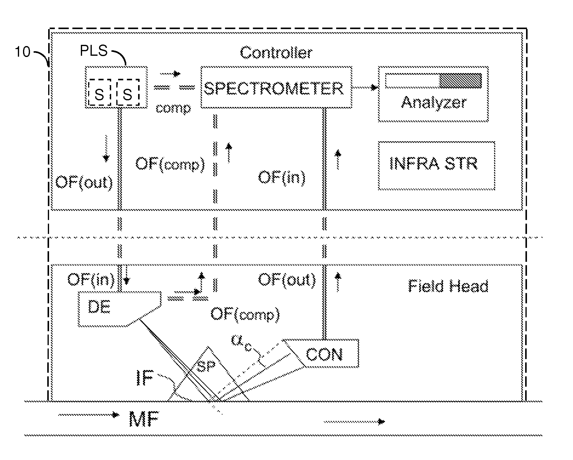
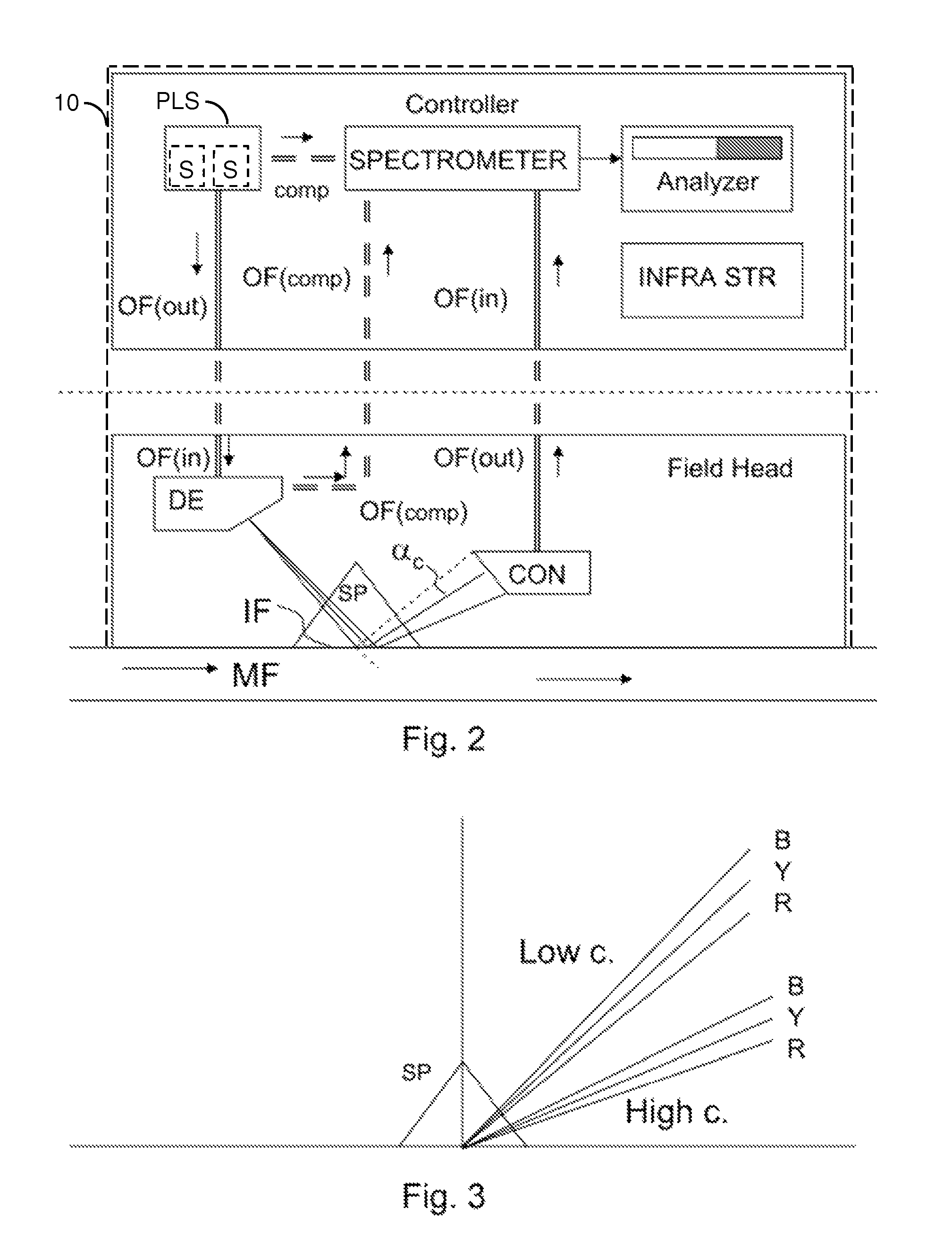
[0059]FIG. 2 illustrates an optical system comprising at least one field head and at least one controller of a field head according to an embodiment of the invention. The number of field heads and / or controllers in a system is not limited to the mere illustrated, as a skilled man in the art understands from the embodiments of the invention. Although there is a dashed line illustrated in FIG. 2 there between the field head and the controller indicative of remoteness, according to an embodiment they can be assembled into the same cover 10, shown in dashed lines, to comprise a single instrument. In this kind of embodiments, the number of field heads under the same controller's control is not limited, neither the number of remote field head units pluggable to the device, but nor for the internally connected field heads. The wave guide can be used for separating the field head and the controller, for example one in a first room and the other in a second room or space.

[0060]FIG. 2 illustr...


PUM

PropertyMeasurementUnit
critical angle αcaaaaaaaaaa
optical instrumentaaaaaaaaaa
refractive indexaaaaaaaaaa

Abstract

An optical instrument includes a controller and a field head arranged for measuring the refractive index of a medium, or a derivable quantity therefrom. The field head includes a measurement prism having a medium-boundary surface, a first wave guide for providing broad-band light from a broad band light source, a dispersive element for dispersing the broad-band light into at least one component light beam of plural component light beams, so that each incident component light beam has a differently directed propagation path and at least one different wave length, and a condenser for collecting at least one component light beam reflected at the medium-boundary surface into a second wave guide. The dispersive element is arranged to direct at least one component light beam into a critical angle of total reflection from the boundary surface, and at least other light beam component into an angle leading into the condenser arranged to collect at least one other component light beam to be passed to a spectrometer. The controller of a field head includes a light source for providing poly-chromatic light into a first wave guide for forming a plurality of component light beams to propagate in the field head and a spectrometer for spectrum analysis of light inputted via at least one input wave guide from the field head.

Description

[0001]This application claims priority from Finnish Patent Application No. 20105110 filed on Feb. 5, 2010, which is incorporated here by reference.FIELD[0002]The field of the invention belongs in a very general level to determination of properties of a medium, but more specifically by utilizing the optical properties of a medium and / or the utilization thereof for a derivable quantity determination, as indicated in the preamble of the independent claim.BACKGROUND[0003]Certain optical instruments can be used for measuring refractive index of a substance, or for determining a derivable quantity as based on its dependence on the refractive index. As an example of such a derivable quantity, the measurement of concentration of a component in a medium substance can be made as based on the refraction index measurement. Other derivable quantities comprise density, content of other substances, conductivity, etc. Such instruments utilizing the same principle may apply in suitable part also for...

Claims


Application Information

Patent Timeline
Patent Type & Authority Patents(United States)
IPC IPC(8): G01N21/41
CPCG01N21/43G01N21/431
Inventor KAHRE, JAN
Owner KAHRE JAN
Why Eureka
Try Eureka