Apparatus and method for modifying a fuel tank to accept an in-tank fuel pump

a technology of in-tank fuel pump and fuel tank, which is applied in the direction of machines/engines, liquid transfer devices, transportation items, etc., can solve the problems of fuel starvation and/or vapor lock, the difficulty of mounting an in-tank fuel pump in an existing tank, and the inability to meet the requirements of the fuel tank. achieve the effect of sufficient resiliency

a technology of in-tank fuel pump and fuel tank, which is applied in the direction of machines/engines, liquid transfer devices, transportation items, etc., can solve the problems of fuel starvation and/or vapor lock, the difficulty of mounting an in-tank fuel pump in an existing tank, and the inability to meet the requirements of the fuel tank. achieve the effect of sufficient resiliency

US8783287B2Active Publication Date: 2014-07-22AEROMOTIVE LLC

Image

  • Apparatus and method for modifying a fuel tank to accept an in-tank fuel pump
  • Apparatus and method for modifying a fuel tank to accept an in-tank fuel pump
  • Apparatus and method for modifying a fuel tank to accept an in-tank fuel pump

Examples


Embodiment Construction

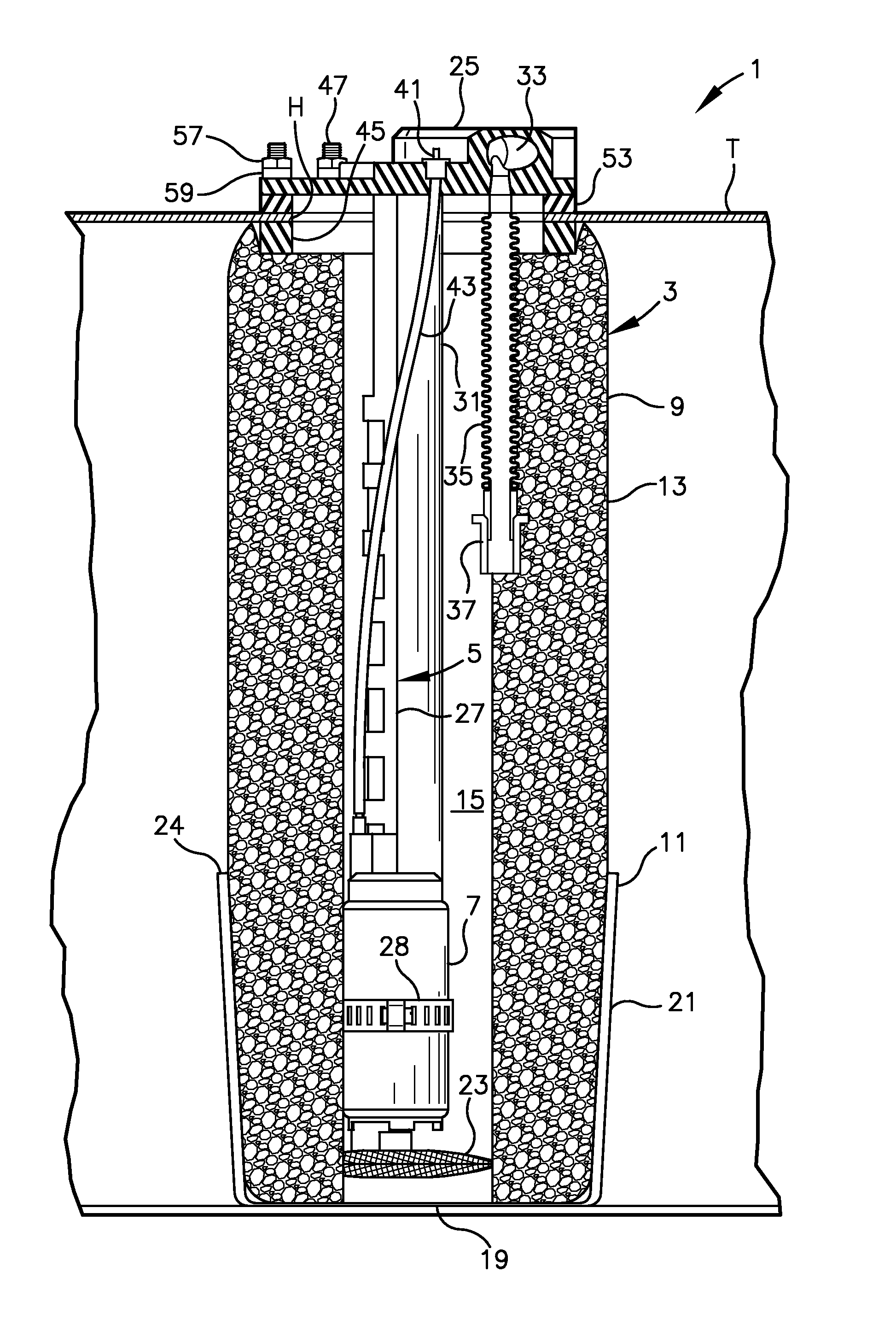
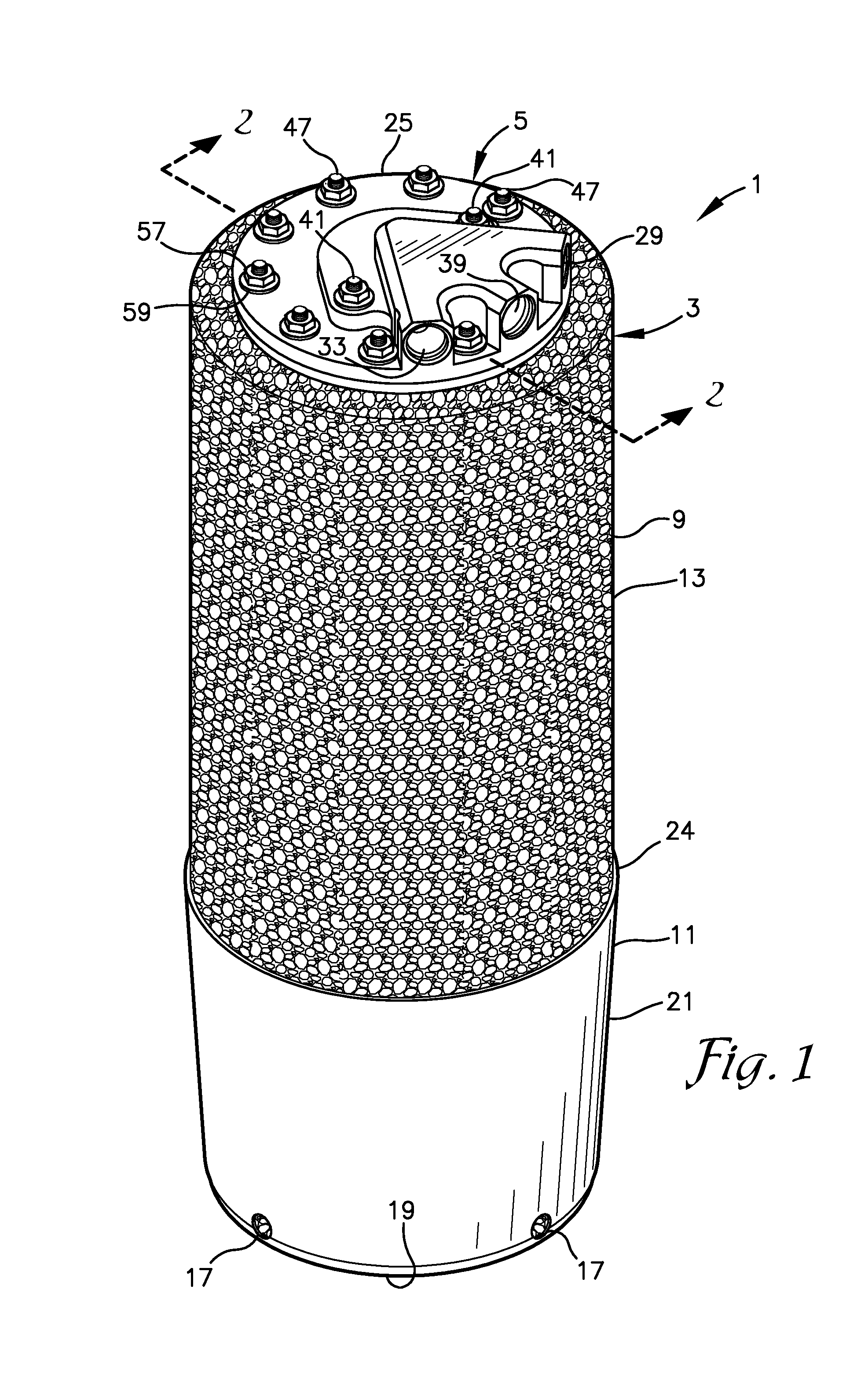
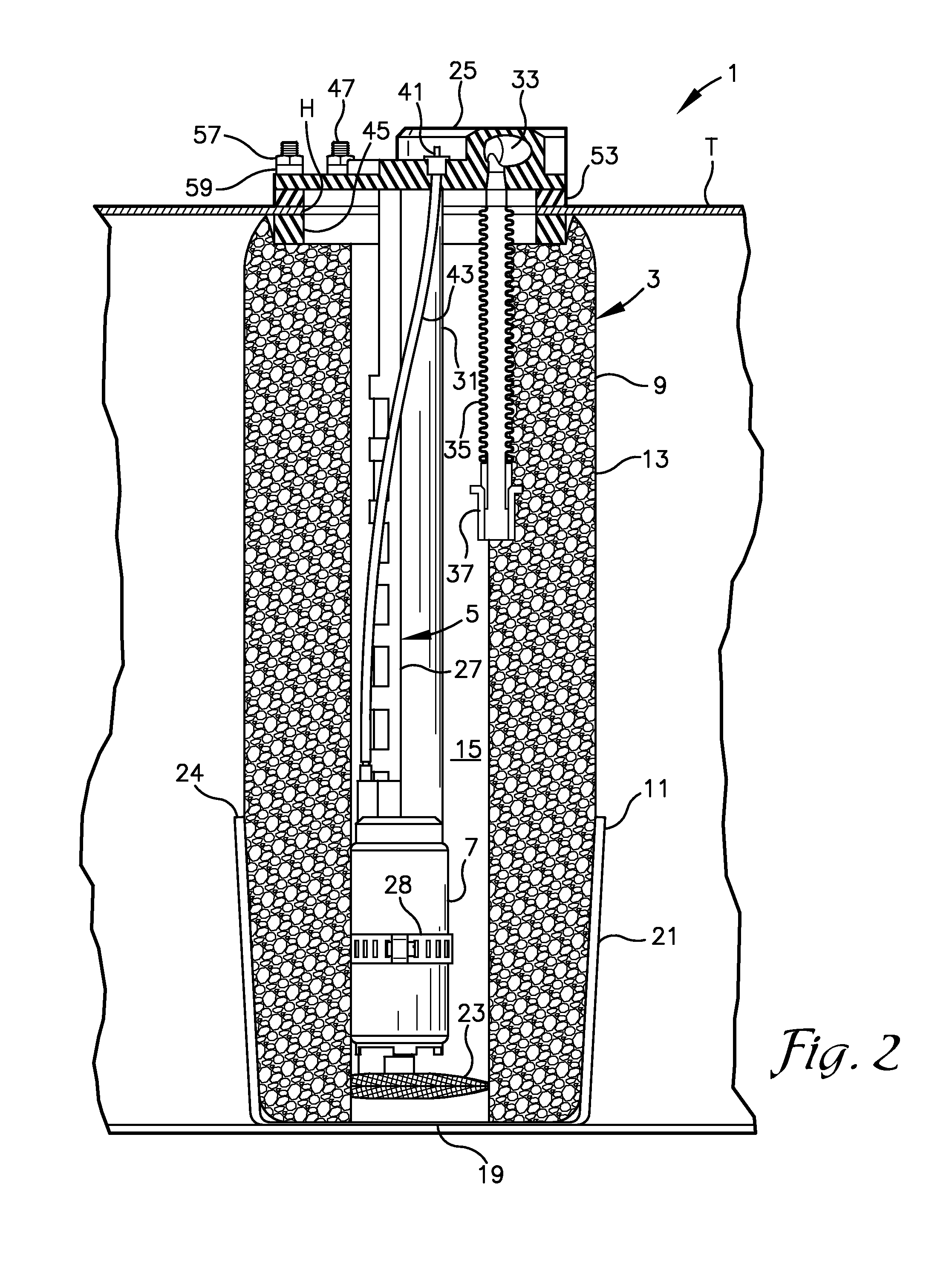
[0021]As required, detailed embodiments of the present invention are disclosed herein; however, it is to be understood that the disclosed embodiments are merely exemplary of the invention, which may be embodied in various forms. Therefore, specific structural and functional details disclosed herein are not to be interpreted as limiting, but merely as a basis for the claims and as a representative basis for teaching one skilled in the art to variously employ the present invention in virtually any appropriately detailed structure. The drawings constitute a part of this specification and include exemplary embodiments of the present invention and illustrate various objects and features thereof.

[0022]Certain terminology will be used in the following description for convenience in reference only and will not be limiting. For example, the words “upwardly,”“downwardly,”“rightwardly,” and “leftwardly” will refer to directions in the drawings to which reference is made. The words “inwardly” a...


PUM

PropertyMeasurementUnit
flexibleaaaaaaaaaa
lengthaaaaaaaaaa
diameteraaaaaaaaaa

Abstract

A baffle has a sidewall and an interior space sized to receive the in-tank pump. The sidewall is formed of a flexible material so as to be longitudinally compressible. The compressibility of the sidewall allows the baffle to be mounted in fuel tanks of varying depths. The baffle is used in a method for mounting an in-tank fuel pump in a fuel tank. The method includes the steps of cutting a hole in a top wall of the fuel tank, inserting the baffle into the tank through the hole, compressing the sidewall of the baffle so that the baffle extends between the top and bottom walls of the tank, installing the in-tank pump in the interior space of the baffle and installing a cover plate over the hole.

Description

[0001]This application claims the benefit of Provisional Application Ser. No. 61 / 702,649 filed Sep. 18, 2012.BACKGROUND OF THE INVENTION[0002]1. Field of the Invention[0003]This invention relates to automotive fuel systems, and in particular to an apparatus and method for modifying a fuel tank to accept an in-tank fuel pump when the tank was not originally designed for use with such an in-tank pump or when an additional in-tank pump is required.[0004]2. Description of the Related Art[0005]Modern automobiles using electronic fuel injection systems utilize a fuel pump mounted inside the fuel tank of the vehicle (hereinafter referred to as an “in-tank pump”) to pick up fuel from the tank and deliver it to the engine. Older automobiles, which typically used carburetors to mix fuel with incoming air, did not use in-tank pumps, but instead relied on mechanical or electric pumps mounted outside of the fuel tank.[0006]Recently, it has become increasingly popular among automobile enthusiasts...

Claims


Application Information

Patent Timeline
22 Jul 2014
Publication
US8783287B2
IPC
B60K15/06; F02M37/14; B60K15/077; F02M37/10
CPC
B60K15/03; B60K2015/03453; B60Y2304/078; B23P11/00; B60K2015/03243; B60K15/03006; B60Y2304/076; B60K2015/03032
Inventors
MATUSEK, STEVEN M.; WESSOL, SHAWN D.