
Flashback blood collection needle

a blood collection needle and needle assembly technology, applied in the field of blood collection devices, can solve the problems of affecting the distension of the vein and the length of the venipuncture procedure, phlebotomist may erroneously believe, and the inability to achieve satisfactory vein entry, so as to prevent leakage of blood, reduce the external profile of the needle assembly, and reduce the effect of needle assembly

Active Publication Date: 2014-08-05
BECTON DICKINSON & CO
View PDF215 Cites 23 Cited by
  • Summary
  • Abstract
  • Description
  • Claims
  • Application Information

AI Technical Summary

Benefits of technology

The patent text describes a needle assembly with a housing having a porous vent positioned inside it. The housing has two end regions with different diameters, and the porous vent can be positioned either between the two regions or spanning the transition between them. The needle assembly can be used to collect blood samples from patients, and the porous vent prevents blood leakage through the needle after it is removed from the patient. The negative pressure created by the porous vent also helps to draw blood into the first chamber of the housing for easy collection into evacuated blood collection tubes. The technical effect of this invention is to improve the safety and efficiency of blood sample collection procedures.

Problems solved by technology

The phlebotomist must ascertain all of these coinciding factors, as such factors may adversely affect the distension of the vein and the length of the venipuncture procedure.
Due to the length of time between vein entry and flashback, the phlebotomist may erroneously believe that satisfactory vein entry has not been achieved since there is no immediate indication of vein entry in the see-through chamber.
The phlebotomist may therefore unnecessarily repeat the venipuncture procedure, requiring replacement of the evacuated container and / or the needle assembly itself.
In such cases, a phlebotomist may use a blood collection set to provide some entry indication, and will then incur the cost of the blood collection set, as well as the cost of a discard tube.

Method used


Image

  • Flashback blood collection needle
  • Flashback blood collection needle
  • Flashback blood collection needle

Examples


Embodiment Construction

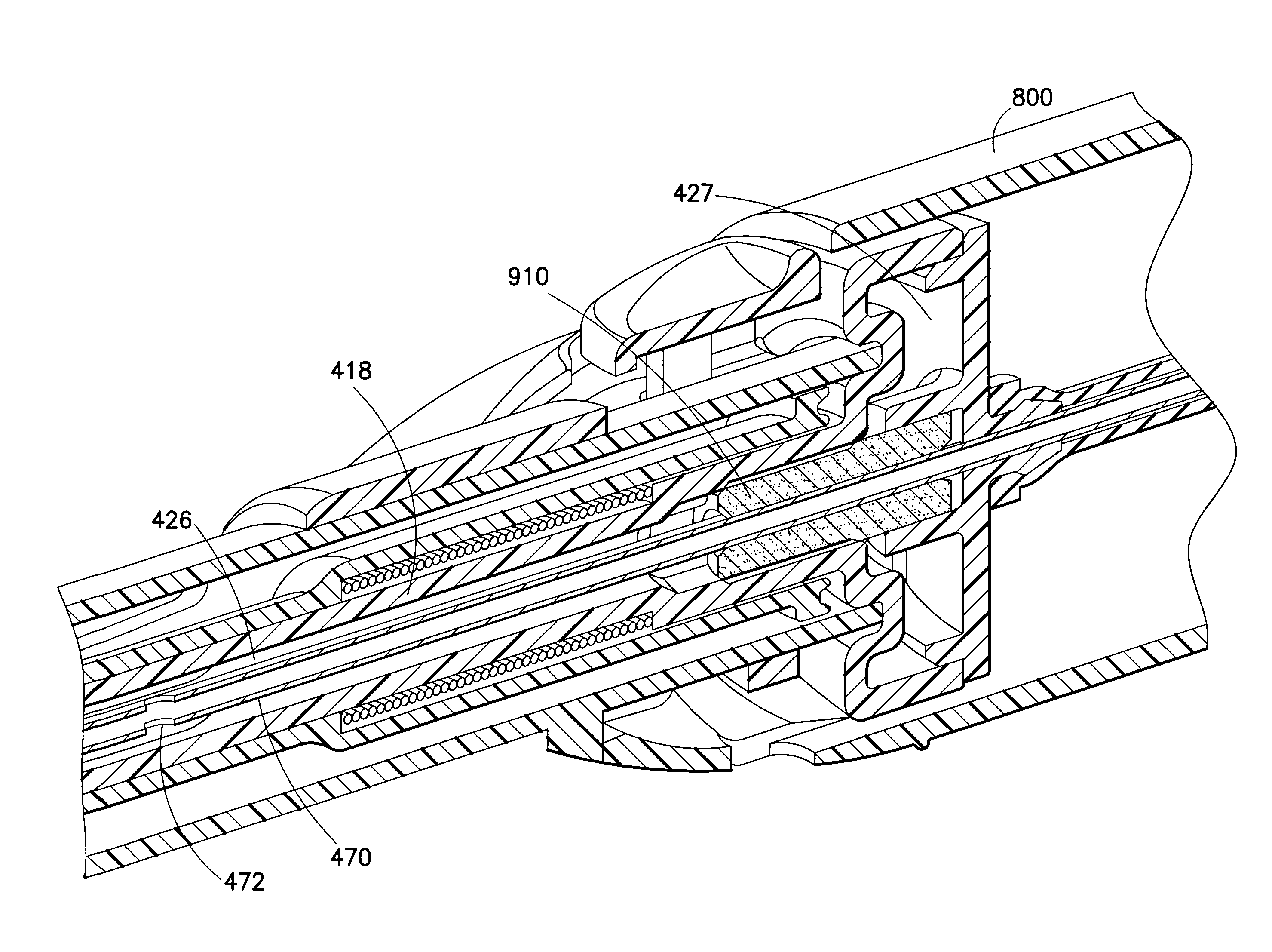
[0038]The invention provides a needle assembly for blood collection that provides a visual indication of vein entry (“flashback”) upon collection of a blood or other fluid sample from a patient into one or more evacuated blood collection tubes and inhibits leakage of the blood or fluid sample from the IV cannula on removal from the patient.

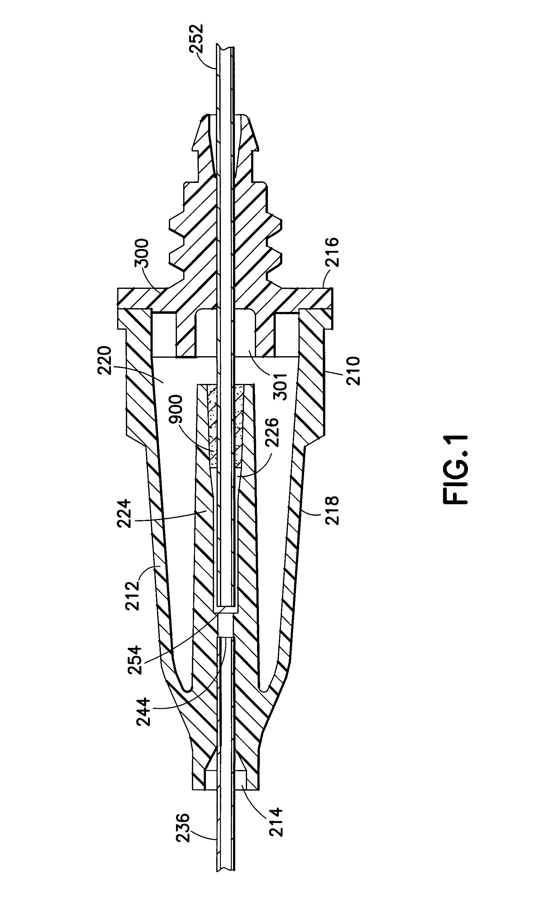
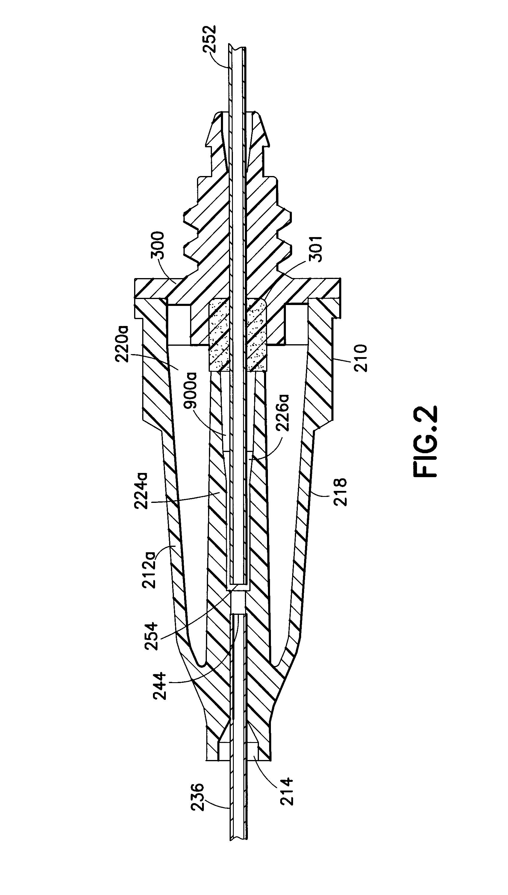
[0039]Various embodiments of the present invention are shown in FIGS. 1-7. With reference to FIG. 1, this embodiment is directed to a needle assembly 210 with a housing 212 having a fluid inlet end 214, a fluid outlet end 216 and a frustum-shaped exterior wall 218 extending between the ends. Exterior wall 218 defines the housing interior 220. Housing 212 further includes a cylindrical interior wall 224 that extends in the housing interior 220 from fluid inlet end 214 substantially concentrically with cylindrical exterior wall 218 to a vent plug 900. Cylindrical interior wall 224 and vent plug 900 define a flashback chamber 226.

[0040]Needle assembl...


PUM


Abstract

A needle assembly includes a transparent or translucent housing with a fluid inlet end, a fluid outlet end, a flashback chamber, and a venting mechanism therebetween. Substantially axially aligned inlet and outlet cannulas extend from the housing and communicate with the chamber. A sealable sleeve covers the external end of the outlet cannula. Relative volumes of the cannulas, the chamber, and the sleeve are selected to provide rapid reliable flashback indicative of venous entry with an internal vent positioned within the housing so as to divide the interior into first and second chambers, with the second chamber being adapted to maintain a negative pressure therein relative to the external environment so as to inhibit leakage of blood from the needle on withdrawal from the patient.

Description

[0001]The present application claims priority to U.S. application Ser. No. 12 / 044,354 filed on Mar. 7, 2008, entitled “Flashback Blood Collection Needle”.BACKGROUND OF THE INVENTION[0002]1. Field of the Invention[0003]The present invention relates to a device for collecting blood samples by performing venipuncture on a patient. More particularly, the present invention relates to a needle assembly for multiple sample blood collection that allows a phlebotomist to determine whether vein entry has occurred when collecting a blood sample from a patient into an evacuated blood collection tube.[0004]2. Description of Related Art[0005]Venipuncture is the primary method used for acquiring blood samples for laboratory testing. In performing venipuncture procedures, a phlebotomist must follow several steps simultaneously. Such steps include assessing the patient's overall physical and psychological condition so as to properly select a venipuncture site and technique. The phlebotomist must als...

Claims


Application Information

Patent Timeline
Patent Type & Authority Patents(United States)
IPC IPC(8): A61B5/00A61B5/15B65D81/00
CPCA61B5/1422A61B5/15003A61B5/150213A61B5/150259A61B5/150389A61B5/150496A61B5/150572A61B5/150633A61B5/150671A61B5/150732A61B5/1535A61B5/1545A61B5/150488
Inventor TAN, CHEE LEONG ALVINMOH, JONSIM, STANLEY
Owner BECTON DICKINSON & CO
Learn More