[0014]In a particular embodiment, the first end of the housing comprises an elongated longitudinal first portion having a first
diameter and the second end of the housing comprises a second portion having a second
diameter larger than the first
diameter of the first portion. In such an embodiment, the porous vent may be positioned within the housing interior between the first portion having a first diameter and the second portion having a second diameter. Alternatively, the porous vent may be positioned within the housing interior at a location spanning the transition between the first diameter of the first portion and the second diameter of the second portion. In embodiments where the second chamber includes multiple interior regions, such as a first interior region and a second interior region, the first chamber may extend along a portion of the longitudinal first portion, with at least one of the interior regions, such as the second interior region of the second chamber extending longitudinally concentrically about the first chamber. In this manner, the external diameter, and thus the external profile of the needle assembly, can be decreased.
[0015]In yet a further embodiment, a method of preventing leakage, such as, for example, blood droplets, at the patient puncture tip in a needle assembly is provided. The method involves receiving blood through a patient puncture tip and into a first chamber of a needle assembly, with the needle assembly including a needle housing defining a housing interior; a cannula having the patient puncture tip extending from a first end of the needle housing; a non-patient puncture tip extending from a second end of the needle housing, the non-patient puncture tip and the patient puncture tip being in fluid communication with each other through the cannula; and a porous vent positioned within the housing interior and separating the housing interior into a first chamber and a second chamber. The cannula is in fluid communication with the first chamber such that the sole communication path between the housing interior and the external environment is via the patient puncture tip, and the porous vent includes pores for passage of blood therethrough from the first chamber into the second chamber. Fluid communication is established between the non-patient puncture tip and an evacuated collection container, such that blood contained within the first chamber is drawn into the evacuated collection container and air is drawn out of the second chamber through the porous vent. As such, a negative pressure is established within the second chamber relative to the external environment of the needle assembly, such that blood flows through the cannula into the first chamber and contacts the porous vent. Blood is then drawn through the pores of the porous vent toward the second chamber such that after removing the patient puncture tip from the vasculature of the patient any blood contained within the cannula is displaced away from the patient puncture tip toward the second chamber based upon the negative pressure established within the second chamber.
[0017]In yet a further embodiment, the invention is directed to a method of collecting a sample of blood from a patient into an evacuated
blood collection tube using a blood collection assembly having a patient needle tip and a non-patient needle tip and a housing having a flashback
visualization chamber. The method involves using a needle assembly comprising a housing having a porous vent positioned therein to separate an interior of the housing into a first chamber forming the flashback
visualization chamber and a second chamber, the first chamber and second chamber being configured such that air is drawn out of the second chamber through the porous vent and into the evacuated
blood collection tube along with the blood sample, thereby establishing a negative pressure within the second chamber. The negative pressure causes blood to be drawn into the first chamber and contact the porous vent, such that after the patient needle tip is removed from the patient, the negative pressure within the second chamber draws blood from the patient needle tip toward the second chamber, thereby preventing leakage of blood from the patient needle tip after removal from the patient.
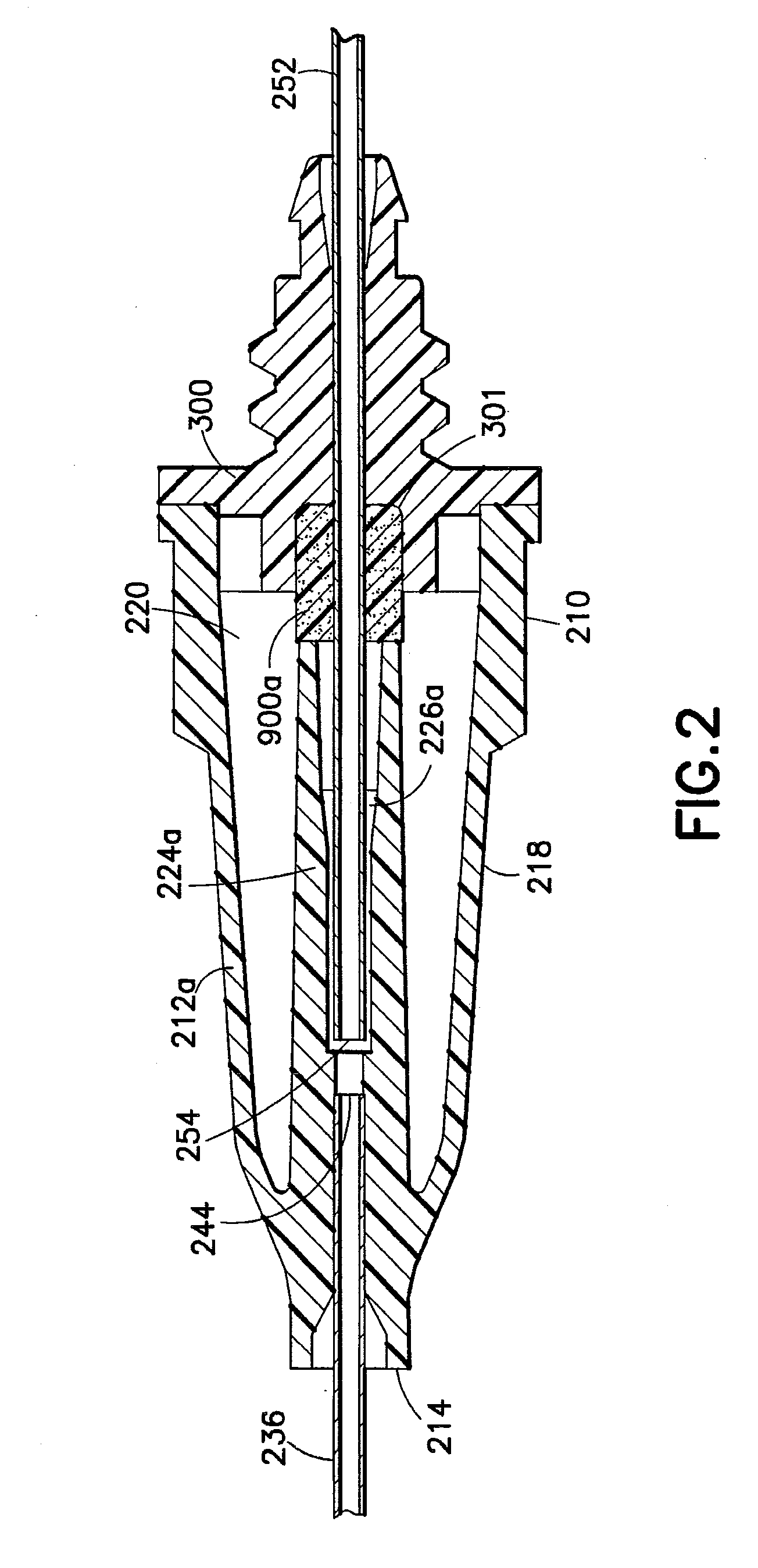
[0020]According to one design, the at least one cannula can comprise a single cannula extending through the housing. The single cannula can include a lumen extending therethrough, a first end comprising the patient puncture tip, a second end comprising the non-patient puncture tip, and an opening through the cannula into the lumen at a location between the first end and the second end providing fluid communication between the lumen of the cannula and the first chamber of the housing. According to another embodiment, the at least one cannula can comprise a first cannula extending from the housing and comprising the patient puncture tip, and a second cannula extending from the housing and comprising the non-patient puncture tip. The first cannula and the second cannula are substantially axially aligned within the housing interior and separated from each other by a gap in fluid communication with the first chamber of the housing. The first chamber and the second chamber are configured such that upon
insertion of the patient puncture tip into a patient causes blood to flow into the first chamber without sealing the porous vent, and upon application of a negative pressure source to the non-patient puncture tip, blood and air are drawn from the first chamber and air is drawn from the second chamber, thereby establishing a negative pressure within the second chamber with respect to an external environment of the needle assembly. Upon removal of the patient puncture tip from the patient, the negative pressure within the second chamber draws blood from the patient needle tip toward the second chamber to prevent blood droplets from being present at the patient puncture tip.
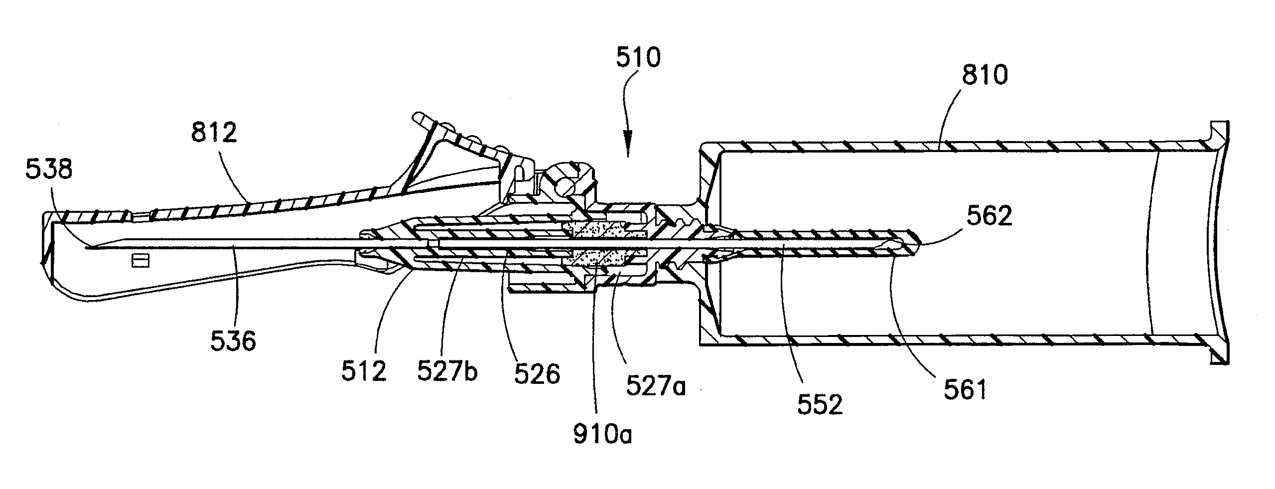
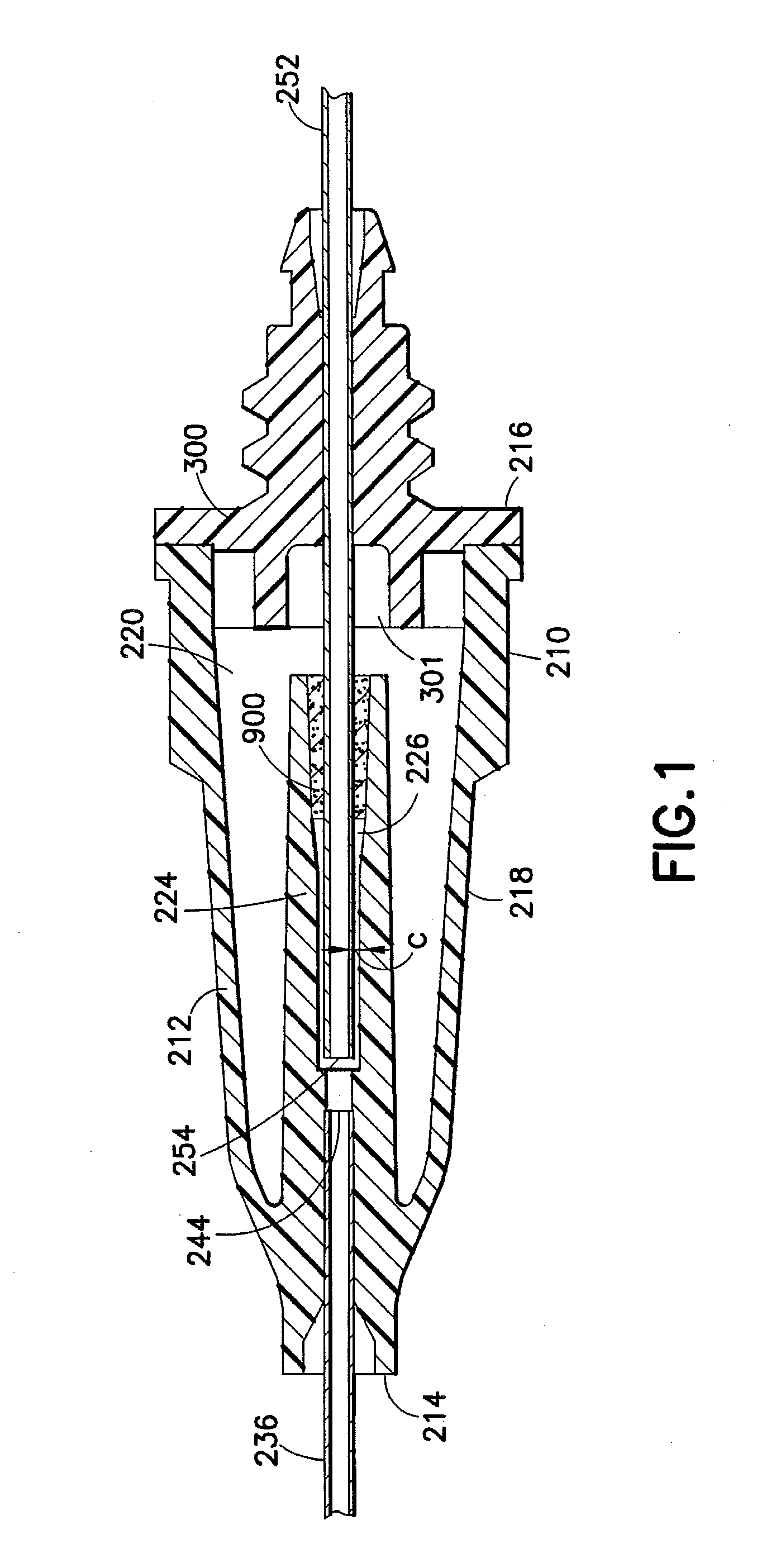
[0022]In another embodiment, the invention relates to a needle assembly comprising a housing defining a housing interior. The housing comprises at least one cannula having a patient puncture tip extending from a first end of the housing and a non-patient puncture tip extending from a second end of the housing. The non-patient puncture tip and the patient puncture tip are in fluid communication with each other within the housing interior. A porous vent is positioned within the housing interior separating the housing interior into a first chamber and a second chamber. The porous vent includes pores for passage of fluid therethrough from the first chamber to the second chamber. The porous vent is configured to
control flow of the fluid such that the fluid flows in an axial direction therethrough. The housing includes a rear hub which can block a back end face of the porous vent. Alternatively, the rear hub can leave a portion of the second end face exposed. The rear hub includes a cylindrical portion extending therefrom. This cylindrical portion extends into the first chamber toward the first end of the housing to define a portion of the first chamber. The needle assembly is designed such that the sole communication path between the housing interior and the external environment is via the patient puncture tip. The porous vent comprises a tubular member having a first end face, a second end face, and a central portion extending between the first end face and the second end face. The tubular member further includes an axial hole configured for surrounding at least a portion of the cylindrical portion extending from the rear hub. The at least one cannula is located within at least a portion of the cylindrical portion. The cylindrical portion extending from the rear hub into the axial hole of the porous vent abuts against the inside surface of the porous vent to act as a blocking member to render a portion of the vent non-porous and to cause the fluid to flow along a controlled longitudinal path and consequently through either a central aperture opening between the first and the second chamber or through either the first end face or the second end face of the porous vent. An
adhesive can be located between an inside surface of the porous vent and an outer diameter of the cannula and / or the cylindrical portion or the inner surface portion of the porous vent can be fused to render this portion non-porous in order to assist in controlling the flow of fluid through the porous vent.

