Flow through system, flow through device and a method of performing a test

a flow system and flow device technology, applied in the field of flow system and flow device, can solve problems such as its application restriction

Active Publication Date: 2014-10-21
ZOETIS DENMARK APS
View PDF32 Cites 4 Cited by
  • Summary
  • Abstract
  • Description
  • Claims
  • Application Information

AI Technical Summary

Benefits of technology

[0009]The object of the present invention is to provide a novel flow through system and device by use of which a qualitative as well as a quantitative detection of a target compound in a liquid can be obtained in a relatively simple and economically feasible way.

Problems solved by technology

However, since quantification cannot be performed with the naked eye and hence an exact amount of an analyte cannot be determined, its application is restricted.

Method used


Image

  • Flow through system, flow through device and a method of performing a test
  • Flow through system, flow through device and a method of performing a test
  • Flow through system, flow through device and a method of performing a test

Examples


Embodiment Construction

[0009]The object of the present invention is to provide a novel flow through system and device by use of which a qualitative as well as a quantitative detection of a target compound in a liquid can be obtained in a relatively simple and economically feasible way.

[0010]This object has been achieved by the invention as it is defined in the claims.

[0011]As it will be clear from the following description, embodiments of the invention achieve other objectives and have other desired and beneficial effects.

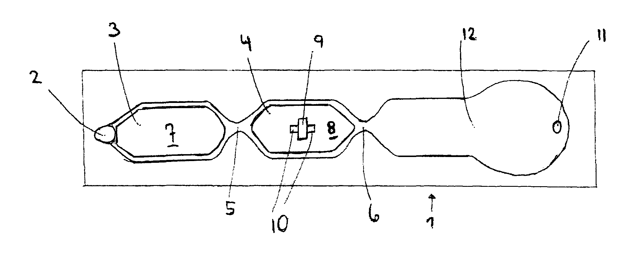
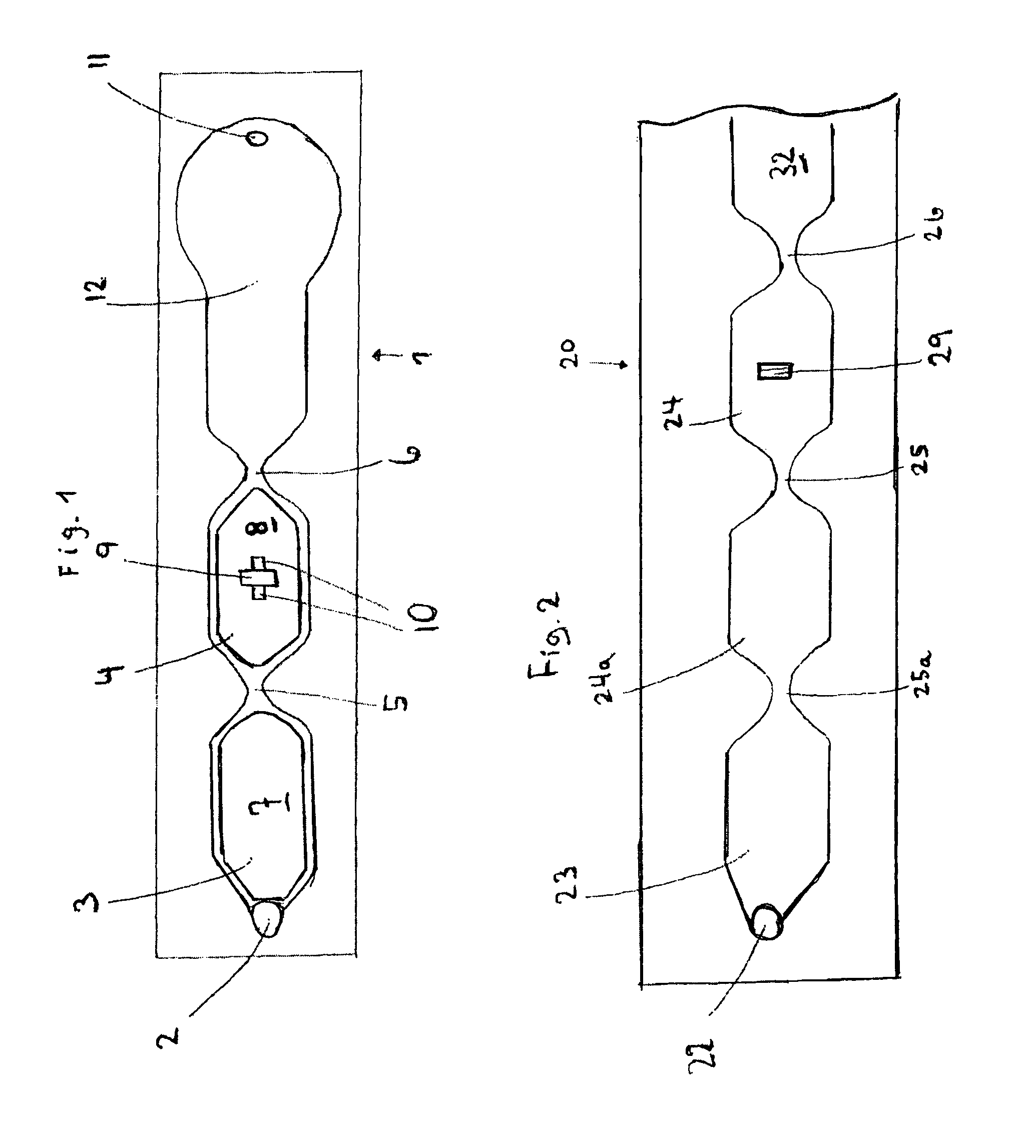
[0012]The flow through system for quantifying a target component in a liquid according to the invention comprises a flow-through device and at least two quantification units, which may or may not be an integrated part of the flow-through device.

[0013]The flow-through device comprises an inlet for the liquid sample to be tested which inlet is placed up stream to the marker section.

[0014]The flow-through device comprises a flow path comprising a marker section, a capture section downstream...


PUM

PropertyMeasurementUnit
distanceaaaaaaaaaa
lengthaaaaaaaaaa
lengthaaaaaaaaaa

Abstract

The invention relates to a flow through system for quantifying a target component in a liquid. The flow through system comprises a flow-through device comprising a flow path comprising a marker section, a capture section downstream to said marker section, and at least two quantification sections. The marker section comprises a non-immobilized marker. The capture section comprises a capture zone with an immobilized capture agent, and the at least two quantification sections comprise a pre-capture quantification section placed downstream to the marker section and up stream to the capture section, and a post-capture quantification section placed downstream to the capture section. The system further comprises a quantification unit for each of said quantification sections. The quantification unit(s) being arranged to quantify marker containing components and / or particles passing through said respective quantification sections. The invention also relates to a flow through device for such flow through system and a method of determining the amount of target component in a liquid using a flow through system.

Description

TECHNICAL FIELD[0001]The invention relates to a flow through system for use in test of a liquid such as a test for the presence of a component in a liquid.BACKGROUND ART[0002]Flow through devices are widely used for performing tests of different types. The tests are generally performed on liquid samples which are applied to channels of for example microfluidic size. The liquid sample is subjected to marker and is flowed over an immobilized capture probe capable of capturing marked target components.[0003]Flow through devices are also referred to as lateral flow devices. Lateral flow devices have generally been used as quantitative assay method which can measure one or more analyte species at the same time, with a relative high sensitivity. Generally prior art lateral flow assay has a structure comprising a sample pad, to which a sample is applied, a releasing pad coated with a detector antibody, a developing membrane (typically nitrocellulose) or strip, in which components of the sa...

Claims


Application Information

Patent Timeline
Patent Type & Authority Patents(United States)
IPC IPC(8): G01N21/77C12M1/00B01L3/00G01N33/558G01N33/53G01N33/543C12M1/34G01N21/75C12Q1/68
CPCG01N33/558B01L3/5027B01L2300/0877G01N33/54366B01L2400/0406B01L2300/0636G01N33/54388
Inventor JONSMANN, JACQUES
Owner ZOETIS DENMARK APS
Why Eureka
Try Eureka