Image lens assembly

a technology of image lens and assembly, which is applied in the field of compact image lens assembly, can solve the problems of easy generation of high-order aberration, inability to effectively suppress the incident angle of off-axis light onto the two lens elements (a fourth lens element and a fifth lens element), and the structure of conventional four-element lens cannot meet the requirements of optical lens system with high-end specifications

Active Publication Date: 2014-11-18
LARGAN PRECISION
View PDF1 Cites 19 Cited by
  • Summary
  • Abstract
  • Description
  • Claims
  • Application Information

AI Technical Summary

Benefits of technology

[0034]Therefore, the refractive angle of the incident light can be reduced by properly distributing the positive refractive power of the fifth lens element and the sixth lens element, so that the high order aberration can be reduced for enhancing the image quality. Moreover, the angle at the peripheral region on the surfaces of the fifth lens element and the sixth lens element would not be excessive for maintaining the relative illumination at the peripheral region of the image.

Problems solved by technology

However, the conventional four-element lens structure cannot satisfy these requirements of optical lens system with high-end specifications.
Although other conventional optical lens systems with five-element lens structure such as the ones disclosed in U.S. Pat. No. 8,000,031 enhance image quality, two lens elements of the optical lens system which closest to an image plane do not have positive refractive power, so that the incident angle of the off-axis light onto the two lens elements (a fourth lens element and a fifth lens element) cannot be effectively suppressed.
Therefore, the high order aberration will be generated easily by the excessive refractive angle of the incident light and the Relative Illumination at a peripheral region of the image cannot be maintained.

Method used


Image

  • Image lens assembly
  • Image lens assembly
  • Image lens assembly

Examples


1st embodiment

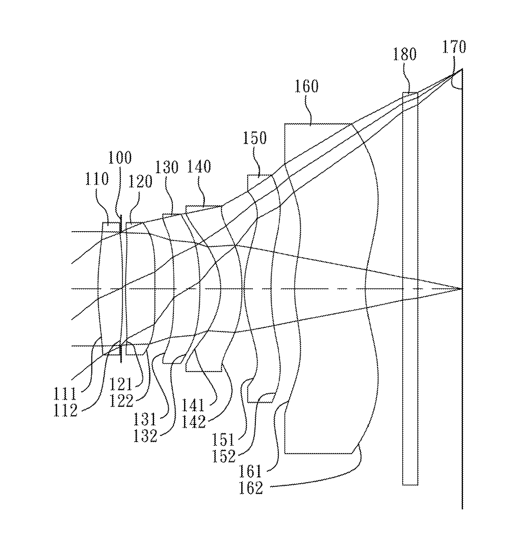
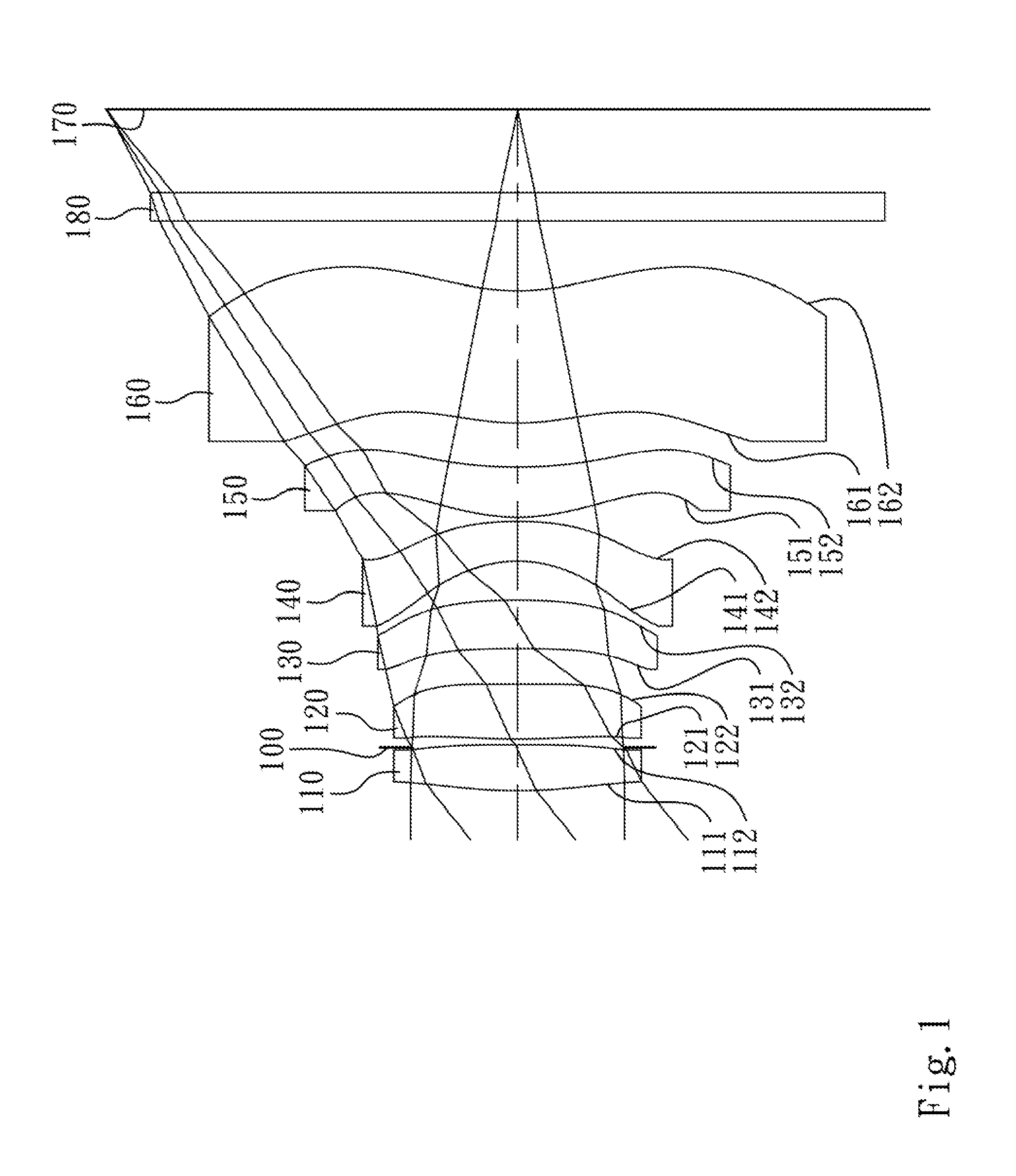
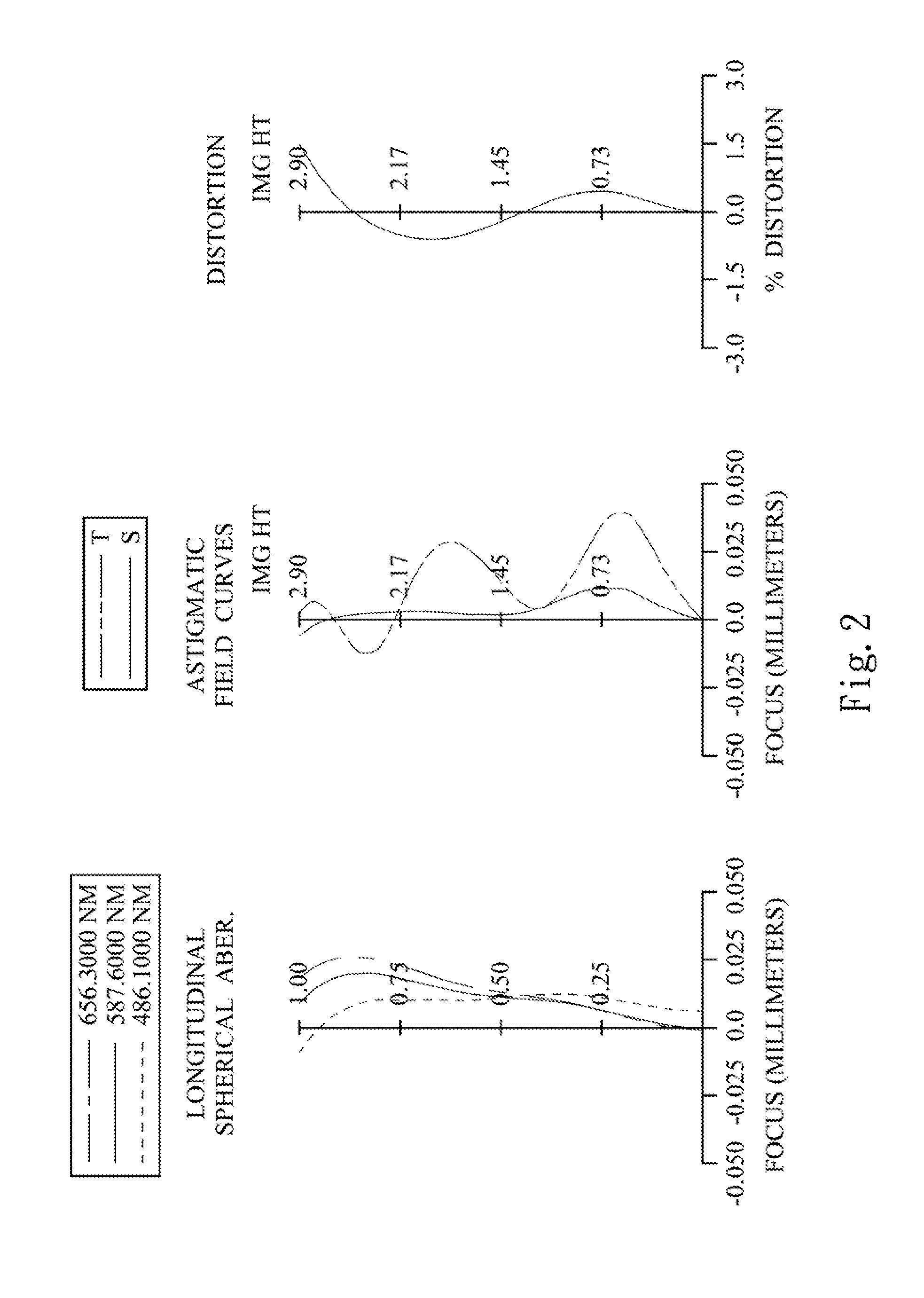
[0054]FIG. 1 is a schematic view of an image lens assembly according to the 1st embodiment of the present disclosure. FIG. 2 shows spherical aberration curves, astigmatic field curves and a distortion curve of the image lens assembly according to the 1st embodiment. In FIG. 1, the image lens assembly includes, in order from an object side to an image side, a first lens element 110, an aperture stop 100, a second lens element 120, a third lens element 130, a fourth lens element 140, a fifth lens element 150, a sixth lens element 160, an IR-cut filter 180 and an image plane 170.

[0055]The first lens element 110 with positive refractive power has a convex object-side surface 111 and a convex image-side surface 112. The first lens element 110 is made of plastic material and has the object-side surface 111 and the image-side surface 112 being aspheric.

[0056]The second lens element 120 with positive refractive power has a convex object-side surface 121 and a convex image-side surface 122. ...

2nd embodiment

[0085]FIG. 3 is a schematic view of an image lens assembly according to the 2nd embodiment of the present disclosure. FIG. 4 shows spherical aberration curves, astigmatic field curves and a distortion curve of the image lens assembly according to the 2nd embodiment. In FIG. 3, the image lens assembly includes, in order from an object side to an image side, a first lens element 210, an aperture stop 200, a second lens element 220, a third lens element 230, a fourth lens element 240, a fifth lens element 250, a sixth lens element 260, an IR-cut filter 280 and an image plane 270.

[0086]The first lens element 210 with positive refractive power has a convex object-side surface 211 and a concave image-side surface 212. The first lens element 210 is made of plastic material and has the object-side surface 211 and the image-side surface 212 being aspheric.

[0087]The second lens element 220 with positive refractive power has a convex object-side surface 221 and a concave image-side surface 222...

3rd embodiment

[0100]FIG. 5 is a schematic view of an image lens assembly according to the 3rd embodiment of the present disclosure. FIG. 6 shows spherical aberration curves, astigmatic field curves and a distortion curve of the image lens assembly according to the 3rd embodiment. In FIG. 5, the image lens assembly includes, in order from an object side to an image side, a first lens element 310, an aperture stop 300, a second lens element 320, a third lens element 330, a fourth lens element 340, a fifth lens element 350, a sixth lens element 360, an IR-cut filter 380 and an image plane 370.

[0101]The first lens element 310 with positive refractive power has a convex object-side surface 311 and a convex image-side surface 312. The first lens element 310 is made of plastic material and has the object-side surface 311 and the image-side surface 312 being aspheric.

[0102]The second lens element 320 with negative refractive power has a convex object-side surface 321 and a concave image-side surface 322....


PUM


Abstract

An image lens assembly includes, in order from an object side to an image side, a first lens element, a second lens element, a third lens element, a fourth lens element, a fifth lens element and a sixth lens element. The first lens element with positive refractive power has a convex object-side surface. The second lens element has refractive power. The third lens element has positive refractive power. The fourth lens element has negative refractive power. The fifth lens element with positive refractive power has a convex object-side surface and a concave image-side surface. The sixth lens element with positive refractive power has a convex object-side surface and a concave image-side surface, wherein the image-side surface thereof changes from concave at a paraxial region to convex at a peripheral region. The fifth and sixth lens elements are made of plastic, and the surfaces thereof are aspheric.

Description

RELATED APPLICATIONS[0001]The application claims priority to Taiwan Application Serial Number 101121925, filed Jun. 19, 2012, which is herein incorporated by reference.BACKGROUND[0002]1. Technical Field[0003]The present invention relates to an image lens assembly. More particularly, the present invention relates to a compact image lens assembly applicable to electronic products.[0004]2. Description of Related Art[0005]In recent years, with the popularity of mobile products with camera functionalities, the demand of miniaturized optical lens systems is increasing. The sensor of a conventional photographing camera is typically a CCD (Charge-Coupled Device) or a CMOS (Complementary Metal-Oxide Semiconductor) sensor. As the advanced semiconductor manufacturing technologies have allowed the pixel size of sensors to be reduced and compact optical lens systems have gradually evolved toward the field of higher megapixels, there is an increasing demand for compact optical lens systems featur...

Claims


Application Information

Patent Timeline
Patent Type & Authority Patents(United States)
IPC IPC(8): G02B3/02G02B13/18G02B9/62
CPCG02B13/18G02B13/0045
Inventor TSAI, TSUNG-HANCHOU, MING-TA
Owner LARGAN PRECISION
Why Eureka
Try Eureka