Touch panel system and electronic device

a technology of electronic devices and touch panels, applied in transmission systems, instruments, computing, etc., can solve the problems of impairment of detection sensitivity of touch operation, likely to affect the sensor provided on the touch panel, and affect the noise of the touch panel, so as to achieve the effect of reliably removing (canceling) a wide variety of noises

Active Publication Date: 2015-04-21
SHARP KK
View PDF62 Cites 10 Cited by
  • Summary
  • Abstract
  • Description
  • Claims
  • Application Information

AI Technical Summary

Benefits of technology

[0046]As described above, a touch panel system of the present invention is configured such that a plurality of vertical electrodes and a plurality of horizontal electrodes are so disposed that (i) as viewed in the direction perpendicular to the vertical electrode surface, the plurality of vertical electrodes include no segment coincident with the plurality of horizontal electrodes and that (ii) the plurality of vertical electrodes and the plurality of horizontal electrodes form a uniform grid having no gap. Accordingly, the present invention provides an effect of reliably removing (canceling) a wide variety of noises reflected in a touch panel. Further, the touch panel system, as placed on a display device, can prevent moire and the like from occurring.

Problems solved by technology

Therefore, a sensor provided on the touch panel is likely to be affected not only by a noise such as a clock generated in the display device but also by other noises coming from the outside.
Such the noises lead to impairment in detection sensitivity for a touch operation.

Method used


Image

  • Touch panel system and electronic device
  • Touch panel system and electronic device
  • Touch panel system and electronic device

Examples


embodiment 1

(1) Configuration of Touch Panel System 1

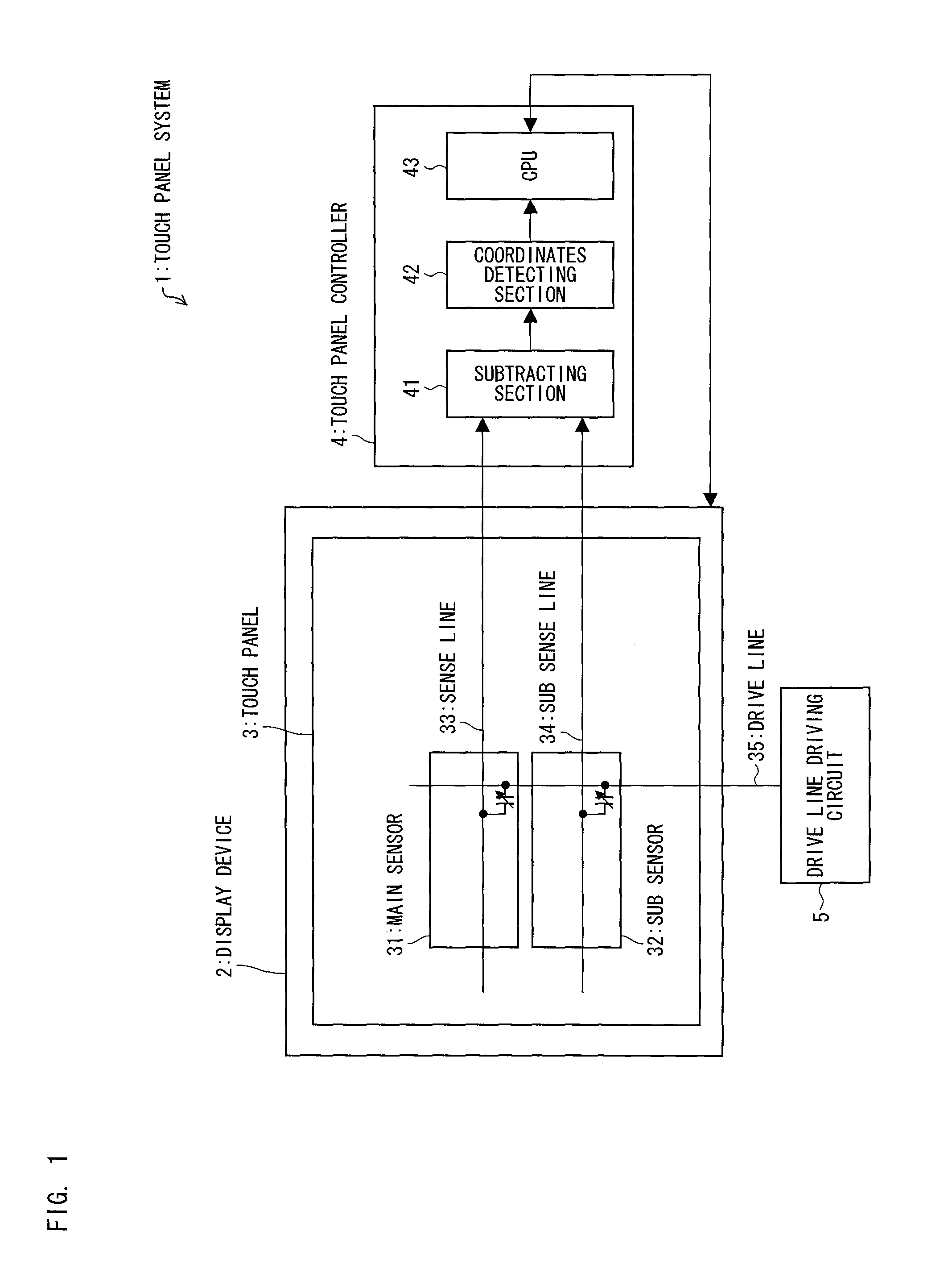
[0128]FIG. 1 is a view schematically illustrating a basic configuration of a touch panel system 1 according to one embodiment of the present invention. The touch panel system 1 includes a display device 2, a touch panel 3, a touch panel controller 4, and a drive line driving circuit 5. Further, the touch panel system 1 has a noise canceling function. In the descriptions below, a side used by a user is referred to as a “front surface” (or an “upper side”).

[0129]The display device 2 includes a display screen (display section), which is not illustrated in FIG. 1. The display screen displays, e.g., various kinds of icons for operation and text information corresponding to operation instructions for the user. The display device 2 is made of, e.g., a liquid crystal display, a plasma display, an organic EL display, or a field emission display (FED). These displays are used in many generally-used electronic devices. Therefore, making the display devi...

embodiment 2

(1) Configuration of Touch Panel System 1a

[0161]FIG. 4 is a view schematically illustrating a basic configuration of a touch panel system 1a according to another embodiment of the present invention. A basic configuration of the touch panel system 1a is substantially the same as that of the touch panel system 1 of Embodiment 1. The following will describe the touch panel system 1a, focusing on differences between the touch panel system 1a and the touch panel system 1. For convenience of explanation, members having the same functions as those explained in the drawings described in Embodiment 1 are given the same reference signs, and explanations thereof are omitted here.

[0162]The touch panel system 1a differs from the touch panel system 1 in terms of configurations of sensors provided in a touch panel 3a. Specifically, the touch panel 3a includes (i) a main sensor group 31a made of a plurality of main sensors 31 and (ii) a sub sensor group 32a made of a plurality of sub sensors 32. T...

embodiment 3

(1) Configuration of Touch Panel System 1b

[0180]FIG. 7 is a view schematically illustrating a basic configuration of a touch panel system 1b according to another embodiment of the present invention. A basic configuration of the touch panel system 1b is substantially the same as that of the touch panel system 1a of Embodiment 2. The following will describe the touch panel system 1b, focusing on differences between the touch panel system 1a and the touch panel system 1b. For convenience of explanation, members having the same functions as those explained in the drawings described in Embodiments 1 and 2 are given the same reference signs, and explanations thereof are omitted here.

[0181]A touch panel 3b has the same configuration of that of the touch panel 3a in the touch panel system 1a of Embodiment 2. Namely, the touch panel 3b includes (i) a plurality of drive lines 35 (in FIG. 7, five drive lines 35), (ii) a plurality of sense lines 33 (in FIG. 7, seven sense lines 33) intersectin...


PUM


Abstract

A touch sensor panel disclosed herein includes: a plurality of vertical electrodes (6); and a plurality of horizontal electrodes (7), the plurality of vertical electrodes (6) and the plurality of horizontal electrodes (7) (i) being so disposed that, as viewed in the direction perpendicular to a substrate, the plurality of vertical electrodes (6) include no segment coincident with the plurality of horizontal electrodes (7) and (ii) forming a uniform grid having no gap.

Description

TECHNICAL FIELD[0001]The present invention relates to a touch panel system and an electronic device including the touch panel system. Particularly, the present invention relates to a touch panel system and an electronic device each of which (i) includes: a plurality of vertical electrodes provided on a vertical electrode surface and arranged at predetermined intervals in a horizontal direction; a plurality of horizontal electrodes provided on a horizontal electrode surface, which is parallel to the vertical electrode surface, and arranged at predetermined intervals in a vertical direction; and an insulator provided between the vertical electrode surface and the horizontal electrode surface to insulate the vertical electrodes from the horizontal electrodes and (ii) is capable of reliably and effectively removing (canceling) a noise generated by a display device, etc.BACKGROUND ART[0002]Recently, introduction of touch panel systems to various kinds of electronic devices has been growi...

Claims


Application Information

Patent Timeline
Patent Type & Authority Patents(United States)
IPC IPC(8): G06F3/045G06F3/041G06F3/044
CPCG06F3/0418G06F3/0416G06F3/044G06F2203/04111G06F3/0446
Inventor MIYAMOTO, MASAYUKIYUMOTO, MANABUYOSHIDA, SHINICHITAKAHAMA, KENGO
Owner SHARP KK
Why Eureka
Try Eureka