Autostereoscopic display method and system

a display method and a technology of autostereoscopic display, applied in the field of three-dimensional (3d) display technologies, can solve the problems of not always fitting all viewers, inconvenient viewing for viewers, and undesired viewing experience for certain viewers

Active Publication Date: 2015-06-09
SUPERD TECH CO LTD
View PDF2 Cites 2 Cited by
  • Summary
  • Abstract
  • Description
  • Claims
  • Application Information

AI Technical Summary

Benefits of technology

[0035]The coupling relationship may impact display quality of the 3D image. For example, for a particular light separation or spectroscopic device, a less number of the display pixels may generate a clearer 3D image display, but the stereoscopic viewing area may be relatively small. On the other hand, if a greater number of the display pixels is used, a wider viewing area may be obtained, but the image clarity may be reduced.
[0009]Other aspects of the present disclosure can be understood by those skilled in the art in light of the description, the claims, and the drawings of the present disclosure.

Problems solved by technology

However, if a viewer is already wearing another type of glasses (such as glasses to correct near-sightedness or far-sightedness), the viewer needs to put on two pairs of glasses overlapping each other in order to watch the stereoscopic display, which makes it inconvenient for the viewer.
In addition, a pair of 3D glasses usually have a fixed width between two legs of the glasses, and thus do not always fit all viewers.
This may cause undesired viewing experience for certain viewers.
However, the light separation device is often unable to completely separate images for the left eye and images for the right eye, which may cause some of the left image seen by the right eye and some of the right image seen by the left eye.
Such crosstalk may result in the “ghost” phenomenon.
However, the cost may be increased significantly.

Method used


Image

  • Autostereoscopic display method and system
  • Autostereoscopic display method and system
  • Autostereoscopic display method and system

Examples


Embodiment Construction

[0018]Reference will now be made in detail to exemplary embodiments of the invention, which are illustrated in the accompanying drawings. Wherever possible, the same reference numbers will be used throughout the drawings to refer to the same or like parts.

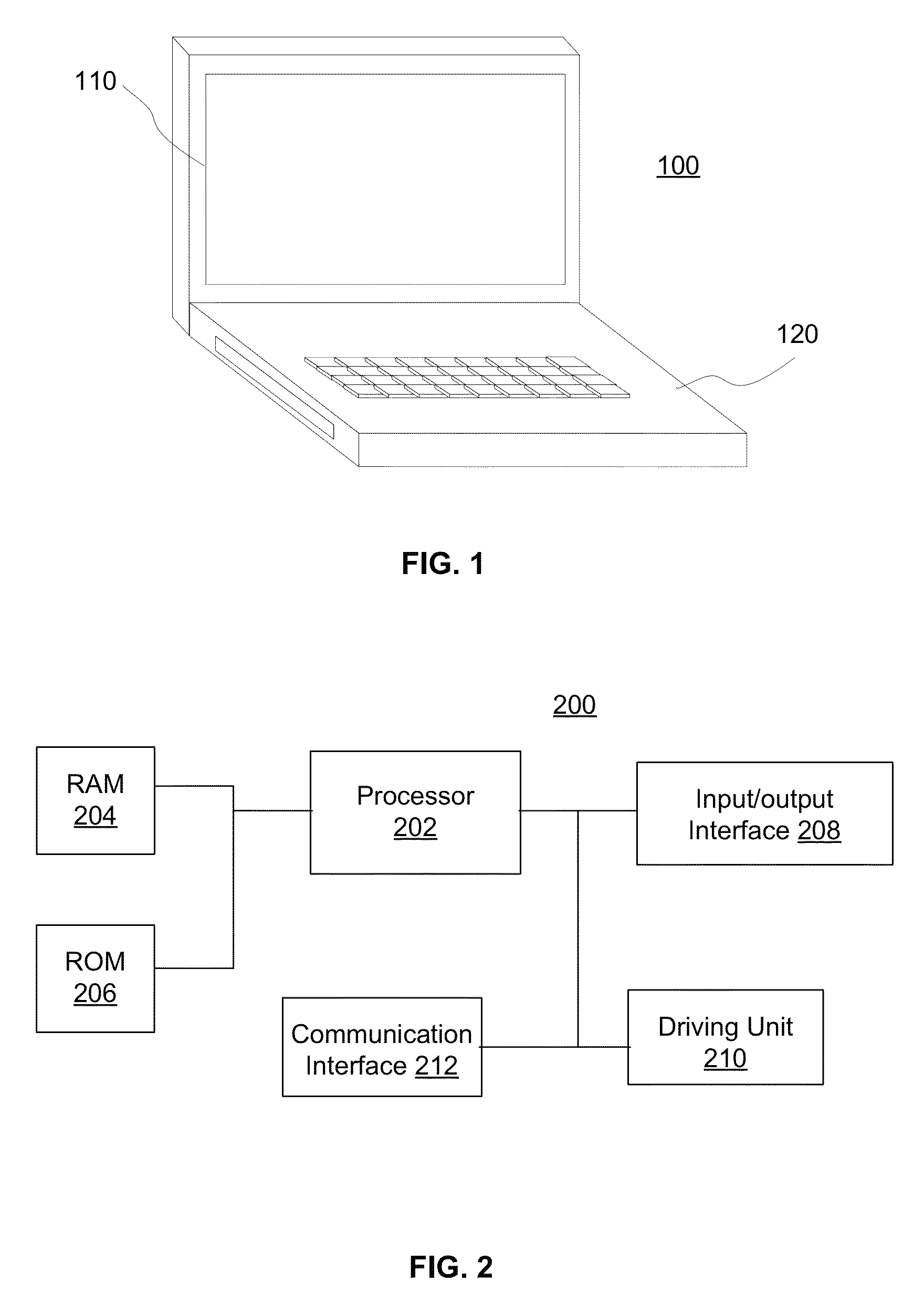
[0019]FIG. 1 illustrates an exemplary environment incorporating certain aspects of the invention. As shown in FIG. 1, a three-dimensional (3D) display system 100 may include a 3D display device 110 and a base 120. The 3D display system 100 may include any appropriate system that is capable of processing and displaying two-dimensional (2D) or 3D images, such as a computer, a television set, a smart phone, or a consumer electronic device. Although 3D display system 100 is shown as a notebook computer, any device with computing power may be used.

[0020]The 3D display device 110 may include any appropriate type of 3D display screen based on plasma display panel (PDP) display, field emission display (FED), cathode ray tube (CRT) display,...


PUM


Abstract

A method is disclosed for a stereoscopic display system. The display system has a display panel containing an array of display units and a plurality of stereoscopic devices coupled to the display panel to affect three-dimensional (3D) display. The method includes receiving a 3D image to be displayed on the array of display units. The method also includes determining original display values for the display units and determining a coupling relationship between the display units and the stereoscopic devices. Further, the method includes determining a crosstalk condition based on the coupling relationship, and adjusting the original display values of display units based on the coupling relationship, the crosstalk condition, and the original display values of both the left display units and the right display units such that the crosstalk condition is cancelled. The method also includes displaying the 3D image using the adjusted display values of the display units.

Description

CROSS-REFERENCES TO RELATED APPLICATIONS[0001]This application claims the priority of Chinese patent application number 201310136018.x, filed on Apr. 18, 2013, the entire contents of which are incorporated herein by reference.FIELD OF THE INVENTION[0002]The present invention generally relates to three-dimensional (3D) display technologies and, more particularly, to the methods and systems for processing and displaying 3D images.BACKGROUND[0003]A person's left eye and right eye are in different horizontal positions separated by a small distance, resulting in two slightly different retinal images viewed by the person's left eye and right eye. The disparity between the different retinal images, observations of scenes from the left eye and the right eye, is called parallax. The human brain processes the different retinal images with the parallax to form a stereoscopic image.[0004]Certain stereoscopic display technologies are based on such parallax concept. Conventional stereoscopic disp...

Claims


Application Information

Patent Timeline
Patent Type & Authority Patents(United States)
IPC IPC(8): H04N13/04
CPCH04N13/0402H04N13/398H04N13/302
Inventor SONG, LEILIU, NINGGE, ZHANG
Owner SUPERD TECH CO LTD
Why Eureka
Try Eureka