Electrical connector with a metal plate for preventing electromagnetic interference

a technology of electromagnetic interference and electric connector, which is applied in the direction of electrical equipment, connection, coupling device connection, etc., to achieve the effect of preventing electromagnetic interferen

Active Publication Date: 2015-08-11
HON HAI PRECISION IND CO LTD
View PDF11 Cites 19 Cited by
  • Summary
  • Abstract
  • Description
  • Claims
  • Application Information

AI Technical Summary

Benefits of technology

[0007]Accordingly, an object of the present invention is to provide an electrical connector securely fixed to a printed circuit board and preventing EMI (electromagnetic interference).
[0008]To achieve the above object, an electrical connector includes an insulative housing, a plurality of contact terminals, a metal plate, and a metallic shell enclosing the insulative housing. The contacts and the metal plate are retained in the insulative housing. The insulative housing includes a base portion and a tongue portion extending forward from the base portion. The contact includes a contacting portion, a tail, and a connecting portion connecting the contacting portion and the tail. The tails are positioned out of the insulative housing. The metal plate has one or more positioning end portions. The positioning end portions are soldered on a printed circuit board for grounding. The electrical connector has improved EMI effect.

Problems solved by technology

However, the metal plate is not designed for mounting to a printed circuit board such that the metal plate does not shield EMI.
However, the metal plate also is not designed to be mounted to a printed circuit board such that the metal plate does not shield EMI.

Method used


Image

  • Electrical connector with a metal plate for preventing electromagnetic interference
  • Electrical connector with a metal plate for preventing electromagnetic interference
  • Electrical connector with a metal plate for preventing electromagnetic interference

Examples


Embodiment Construction

[0015]Reference will now be made in detail to the preferred embodiment of the present invention.

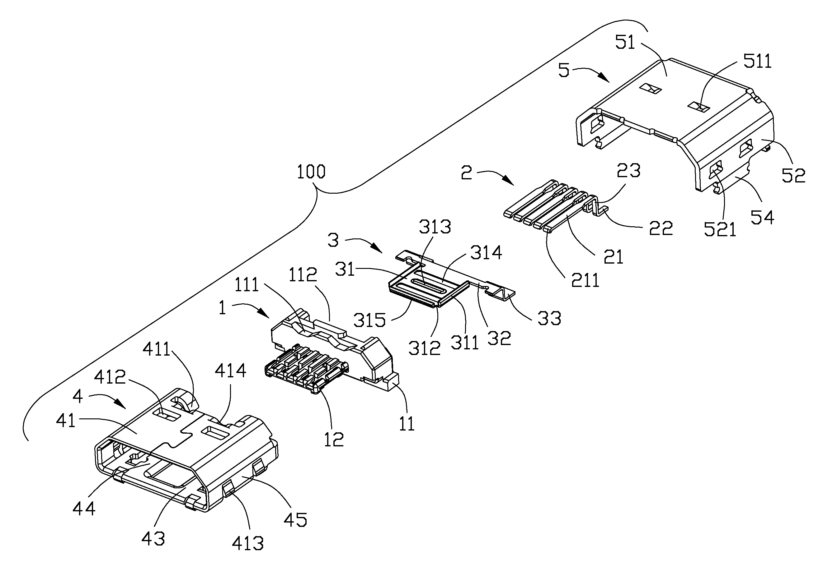
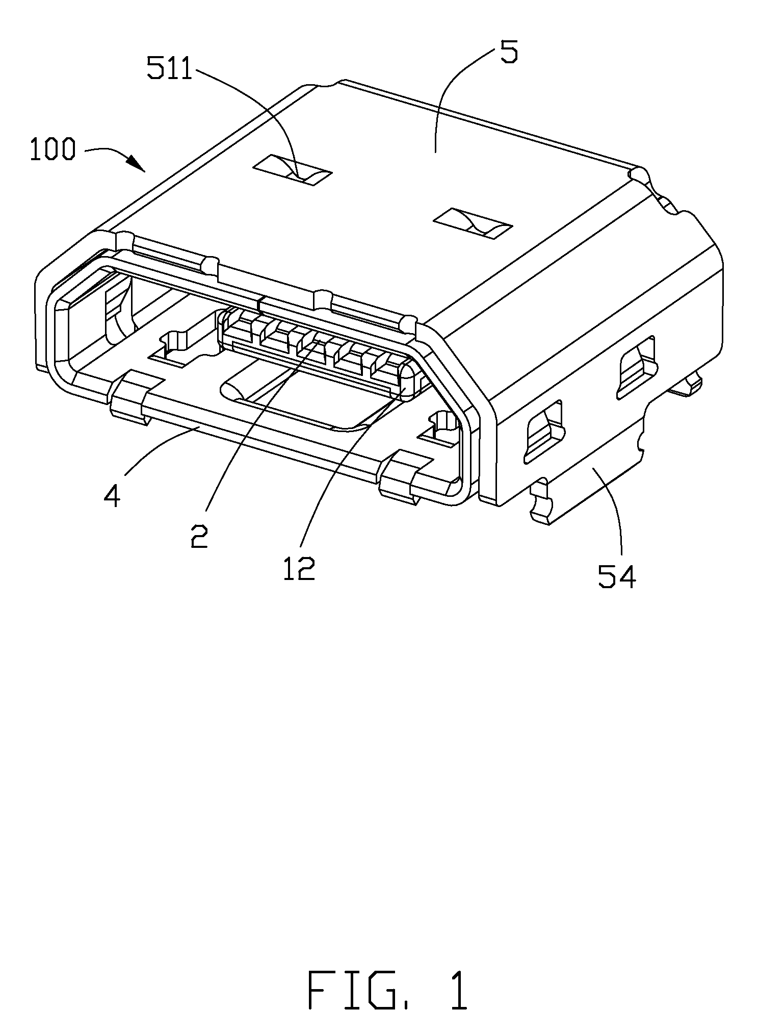
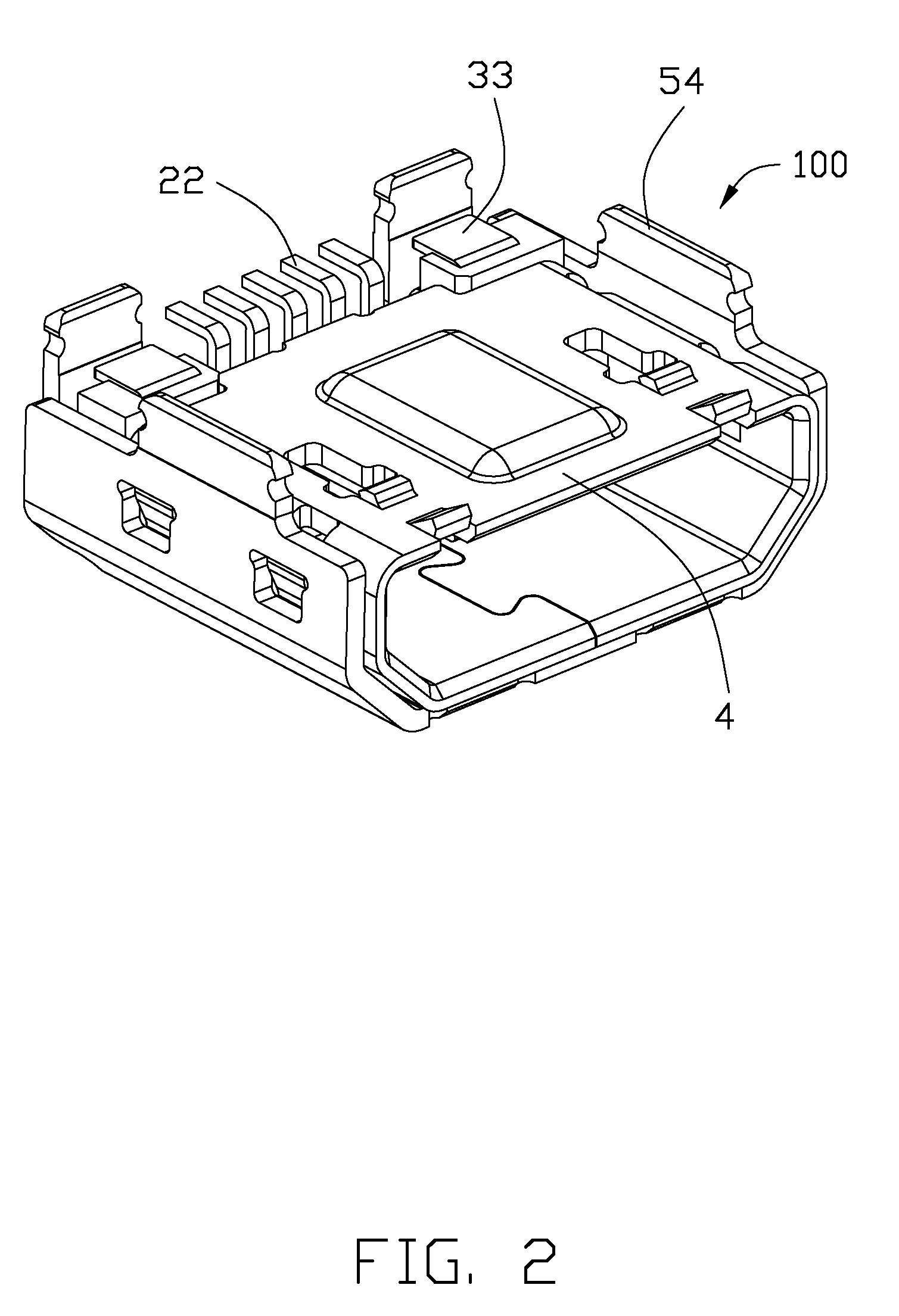
[0016]Referring to FIGS. 1 to 5, an electrical connector 100 includes an insulative housing 1 with a number of contact terminals 2 held therein, a metallic shell 4 defines a receiving room 44 and combined to the insulative housing 1, a sub-shell 5 covering the metallic shell 4 and a metal plate 3 retained in the insulating housing 1 for reinforcing rigidity of the insulative housing. According to the illustrated embodiment of the present invention, the electrical connector 100 is regarded as a micro USB (Universal Serial Bus) interface.

[0017]Referring to FIGS. 3 to 5, the insulating housing 1 comprises a base portion 11 and a tongue portion 12 extending forwardly from the base portion 11 and forwardly into the receiving room 14 of the metallic shell 4. A upper surface of the base portion 11 defines a pair of notches 111 through a front surface of the base portion 11 and a slot 112 through...


PUM


Abstract

An electrical connector (100) includes an insulative housing (1), a number of contact terminals (2), a metal plate (3), and a metallic shell (4) enclosing the insulative housing (1). The terminals and the metal plate (3) are retained in the insulative housing (1). The insulative housing (1) includes a base portion (11) and a tongue portion (12) extending forward from the base portion (11). The contact terminal includes a contacting portion (21), a tail (22), and a connecting portion (23) connecting the contacting portion (21) and the tail (22). The tails (22) are positioned out of the insulative housing (1). The metal plate (3) has a number of positioning end portions (33). The positioning end portions (33) are soldered on a printed circuit board for grounding. The electrical connector (100) has improved electromagnetic interference effect.

Description

BACKGROUND OF THE INVENTION[0001]1. Field of the Invention[0002]The present invention relates generally to an electrical connector, and more particularly to an electrical connector a metal plate for reinforcing rigidity of the insulative housing.[0003]2. Description of Related Arts[0004]Universal Serial Bus (USB) interfaces are widely used in various electronic devices. In recent years, a micro USB interface is introduced to meet miniaturization requirement of electronic devices. U.S. Pat. No. 8,215,997 B2 discloses an electrical connector comprising a metallic shell, an insulating housing assembled to the metallic shell, and a plurality of terminals retained in the insulating housing by insert-molding. The insulating housing has a base portion and a tongue portion extending forwardly from the base portion. Each terminal includes a contact portion exposed to a lower surface of the tongue portion, a soldering portion extending out of a back wall of the base portion, and a connecting ...

Claims


Application Information

Patent Timeline
Patent Type & Authority Patents(United States)
IPC IPC(8): H01R9/03H01R13/6594H01R13/6581
CPCH01R13/6594H01R13/6581
Inventor ZHAO, JUNGUO, JING-JIE
Owner HON HAI PRECISION IND CO LTD
Why Eureka
Try Eureka