3D image signal processing apparatus

a signal processing and 3d technology, applied in the field of 3d (dimensions) image signal processing apparatus, can solve the problems of limited frequency of vertical synchronization and resolution of 3d image displayabl

Active Publication Date: 2016-01-26
SHARP NEC DISPLAY SOLUTIONS LTD
View PDF8 Cites 0 Cited by
  • Summary
  • Abstract
  • Description
  • Claims
  • Application Information

AI Technical Summary

Benefits of technology

The invention allows for handling of 3D image input signals that exceed the maximum transmission rate for the display circuit without adding any frame memory.

Problems solved by technology

That is, the resolution of the image displayable in 3D and the frequency of the vertical synchronization are limited.

Method used


Image

  • 3D image signal processing apparatus
  • 3D image signal processing apparatus
  • 3D image signal processing apparatus

Examples


Embodiment Construction

[0035]One exemplary embodiment according to the present invention will be described in detail with reference to the drawings.

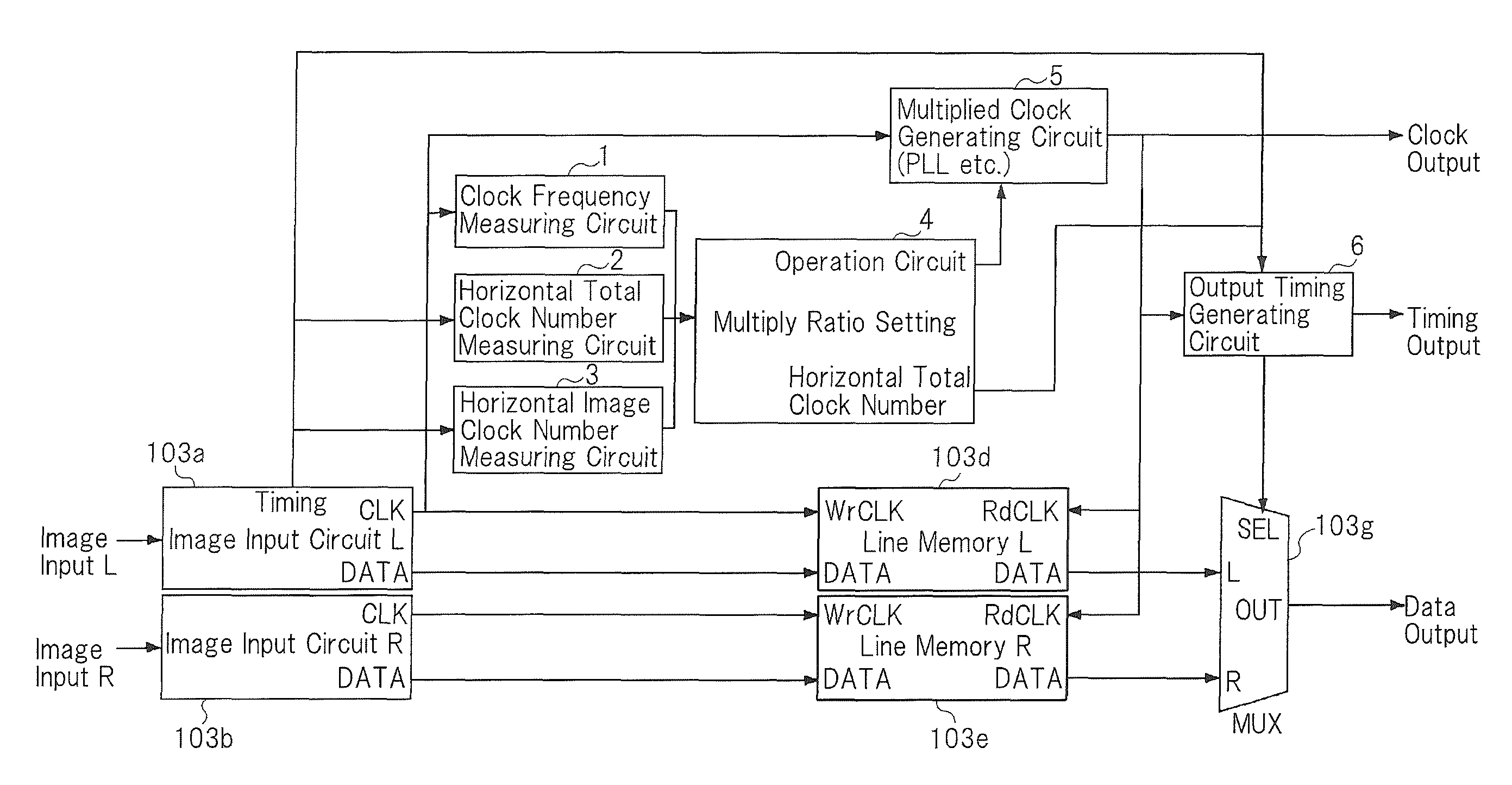
[0036]FIG. 5 is a block diagram showing image input circuit 103-1 as an example of a 3D image signal processing apparatus of one exemplary embodiment of the present invention. Herein, image input circuit 103-1 is used as image input circuit 103 shown in FIG. 2. In FIG. 5, the same components as those in FIG. 3 are allotted the same reference numerals.

[0037]Image input circuit 103-1 includes input image signal clock frequency measuring circuit (first measuring means) 1, horizontal total clock number measuring circuit (second measuring means) 2, horizontal image clock number measuring circuit (third measuring means) 3, operation circuit (determining means) 4, multiplied clock generating circuit (first generating means) 5 such as PLL or the like, and output timing generating circuit (second generating circuit) 6, in addition to the configuration shown in FIG. 3. ...


PUM


Abstract

In 3D display, when double the frequency of the input clock exceeds the maximum rate of transmission to cinema display circuit 104, the multiply ratio of the clock is lowered from 2× multiplication and the output horizontal total clock number is reduced accordingly.

Description

TECHNICAL FIELD[0001]The present invention relates to a 3D (Dimensions) image signal processing apparatus, in particular, to a 3D image signal processing apparatus for combining the left-eye image signal and the right-eye image signal for every frame.BACKGROUND ART[0002]There have been known movie projectors for displaying a 3D image (which will be referred to hereinbelow as “3D image processing apparatus).[0003]FIG. 1 is a block diagram showing a 3D projector.[0004]In FIG. 1, the 3D projector includes input terminal 101 for receiving the left-eye image signal, input terminal 102 for receiving the right-eye image signal, image input circuit 103 and cinema display circuit 104.[0005]Image input circuit 103 receives the left-eye image signal from input terminal 101 and receives the right-eye image signal from input terminal 102. Here, the frame period of the left-eye image signal and the frame period of the right-eye image signal are the same.[0006]FIG. 2 is a diagram for illustrating ...

Claims


Application Information

Patent Timeline
Patent Type & AuthorityPatents(United States)
IPC IPC(8): H04N13/00H04N13/04
CPCH04N13/0497H04N13/004H04N13/0048H04N13/0059H04N13/161H04N13/194H04N13/398H04N13/156
InventorHAMAMURA, SHIGEO
OwnerSHARP NEC DISPLAY SOLUTIONS LTD