Assembling apparatus

a technology of assembling apparatus and assembling rod, which is applied in the direction of mechanical equipment, manufacturing tools, and gearing, etc., can solve the problems of inability to obtain linear motion, large or heavy assembling rod, etc., and achieve the effect of small or light weigh

Active Publication Date: 2016-02-02
TOYOTA IND CORP
View PDF8 Cites 0 Cited by
  • Summary
  • Abstract
  • Description
  • Claims
  • Application Information

AI Technical Summary

Benefits of technology

[0006]Accordingly, the shaft member may perform a linear assembling work using movement in the axial direction and a rotational assembly work using axial rotation. In addition, the assembling apparatus may perform both linear assembling work and rotational assembling work using one shaft member. Thus, the assembling apparatus can be manufactured such that it is small and / or lightweight. For example, the apparatus of the invention can be smaller or lighter in weight compared to the assembling apparatus of the related art. Such related art has a dedicated shaft member which performs linear motion and a dedicated shaft member which performs rotational motion.

Problems solved by technology

In such an apparatus, however, linear motion cannot be obtained.
Thus, there is a problem that the assembling apparatus is large or heavy.

Method used


Image

  • Assembling apparatus
  • Assembling apparatus
  • Assembling apparatus

Examples


Embodiment Construction

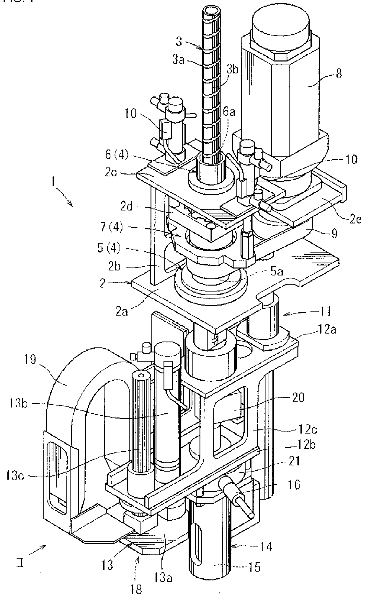
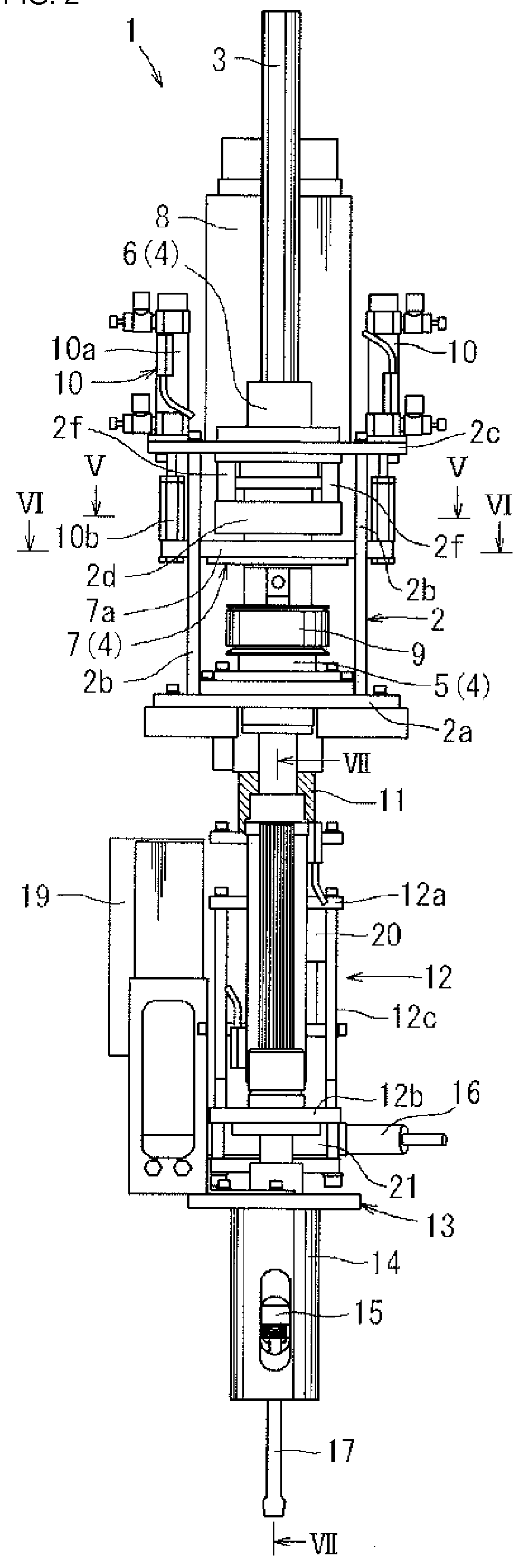
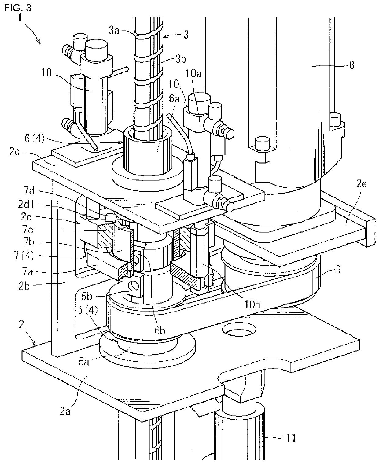
[0014]One embodiment of the present invention is described with reference to FIGS. 1 to 7. As shown in FIG. 1, an assembling apparatus 1 is an apparatus (a multifunctional tool) which may perform a plurality of assembling works required in producing vehicle parts or the like. The assembling apparatus 1 has a base 2, a shaft member 3 and a drive unit (a motor 8 and a power conversion mechanism 4).

[0015]As shown in FIGS. 1 and 2, the base 2 has first to fifth bases 2a to 2e. The first base 2a has a plate-shape and is placed substantially horizontally, and attached to the base 2 wherein it is movable in the horizontal direction using a XY roader (not shown). Second bases 2b stand on both end portions of an upper surface of the first base 2a. A third base 2c is attached to the upper end portion of a pair of second bases 2b. A fourth base 2d is fixed to a lower side of the third base 2c by attachment portions 2f. A fifth base 2e extends laterally from the third base 2c. The motor 8 is mo...


PUM

PropertyMeasurementUnit
torqueaaaaaaaaaa
poweraaaaaaaaaa
movementaaaaaaaaaa

Abstract

An assembling apparatus (1) comprises a shaft member (3) having a linear assembling function and a rotational assembling function, a base (2) supporting the shaft member (3) to be movable in the axial direction and rotatable axially, and a drive unit moving in an axial direction and axially rotating the shaft member (3).

Description

BACKGROUND OF THE INVENTION[0001]Embodiments of the present invention relate to an assembling apparatus which may perform a plurality of types of assembling work.DESCRIPTION OF THE RELATED ART[0002]An assembling apparatus of the related art has a fixed head and a movable head rotatably attached to the fixed head. A screw tightening tool and a grip tool are provided on the movable head (see, Japanese Laid-Open Patent Publication 60-48227). The screw tightening tool and the grip tool can be moved between a use position and a non-use position by rotating the movable head with respect to the fixing head. The screw tightening tool is coupled to an output shaft member provided on the fixed head when located in the use position and axially rotates the screw. The grip tool is coupled to the output shaft member when located in the use position and can grip an article using a pair of arms which rotate at an eccentric position. Accordingly, the assembling apparatus can perform a plurality of a...

Claims


Application Information

Patent Timeline
Patent Type & Authority Patents(United States)
IPC IPC(8): B23P11/00F16H25/08B23P19/04B23P19/06
CPCB23P11/00B23P19/04B23P19/06F16H25/08Y10T29/53Y10T29/53687Y10T29/53848B23P19/02
Inventor WATANABE, NORIYASUMIYAKI, HIROTSUGUTSUGE, HIROSHIYAMAGUCHI, KAZUYUKI
Owner TOYOTA IND CORP
Why Eureka
Try Eureka