Anti-backlash mechanism
- Summary
- Abstract
- Description
- Claims
- Application Information
AI Technical Summary
Benefits of technology
Problems solved by technology
Method used
Image
Examples
first embodiment
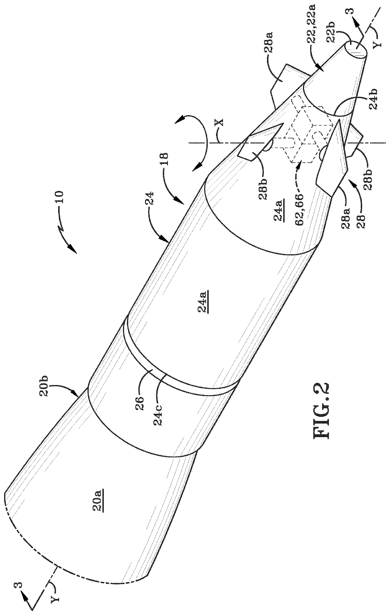
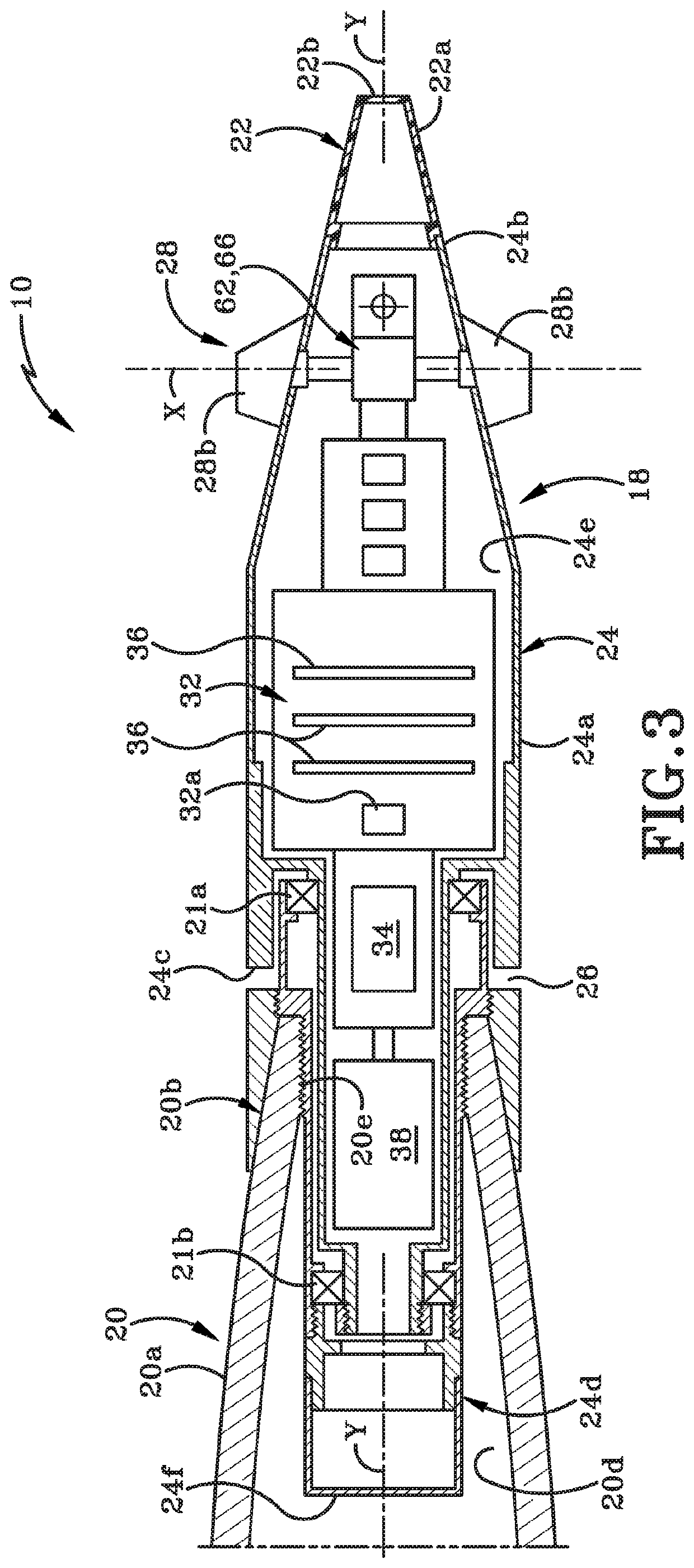
[0044]FIG. 7, which is a cross section view taken from FIG. 5, depicts a partial view of a system for eliminating backlash associated with a guided projectile 10 generally depicted at 60. The system 60 includes a rotation assembly 62, an anti-backlash mechanism 64, and a mechanical ground 66. The rotation assembly 62 includes some components that are substantially similar to the rotation assembly 30 depicted in PRIOR ART FIG. 5, and, as such, those components are denoted with similar reference numerals. In particular, the rotation assembly 62 of the system 60 includes the input shaft 42, the output shaft 44, the first mechanical stop 46, and the second mechanical stop 48 of the PRIOR ART rotation assembly 30 of FIG. 5.
[0045]The first mechanical stop 46 and the second mechanical stop 48 are gears, and, as such, the first mechanical stop 46 may also be referred to as a drive gear 46 and the second mechanical stop 48 may be referred to as a driven gear 48. The drive gear 46 includes a ...
second embodiment
[0052]FIG. 8A is a partial bottom view of a system for eliminating backlash associated with a guided projectile 10 generally depicted at 80 with some components removed for clarity. FIG. 8B is a cross section taken along line 8B-8B of FIG. 8A. The system 80 is substantially identical to the system 60 of FIG. 7 in structure and function with a few exceptions / additions that will be discussed hereafter in greater detail. As shown in FIG. 8A and FIG. 8B, instead of the anti-backlash mechanism 64 being a linear spring, the anti-backlash mechanism 64 is a torsion spring and the system 80 further includes an engagement mechanism 68, which, in this embodiment, is a pin extending from the mechanical ground 66. In this embodiment, the torsion spring is operably engaged with the driven gear 48 on one end and engagement mechanism 68 on the other end. The torsion spring operates in a similar manner as the linear spring and will not be further discussed herein. FIG. 8B also depicts the canard 28b...
third embodiment
[0053]FIG. 9A is a partial bottom view of a system for eliminating backlash associated with a guided projectile 10 generally depicted at 90 with some components removed for clarity. FIG. 9B is a cross section taken along line 9B-9B of FIG. 9A. The system 90 is substantially identical to the system 80 of FIG. 8A except that the anti-backlash mechanism 64 is a different type of torsion spring compared to the torsion spring of FIG. 8A and FIG. 8B. The torsion spring of FIG. 9A and FIG. 9B operates in a similar manner as the torsion spring of FIG. 8A and FIG. 8B and will not be further discussed herein. FIG. 9B also depicts the canard 28b connected to the output shaft 44.
[0054]It will be understood that there are many varieties of torsion springs and, as such, various embodiments can be envisioned using different torsion spring types depending on the particular application.
PUM
 Abstract
Description
Claims
Application Information
 - R&D
- Intellectual Property
- Life Sciences
- Materials
- Tech Scout
- Unparalleled Data Quality
- Higher Quality Content
- 60% Fewer Hallucinations
Browse by: Latest US Patents, China's latest patents, Technical Efficacy Thesaurus, Application Domain, Technology Topic, Popular Technical Reports.
© 2025 PatSnap. All rights reserved.Legal|Privacy policy|Modern Slavery Act Transparency Statement|Sitemap|About US| Contact US: help@patsnap.com


