In the following, the essential points are summarized again by means of groups of characteristics which each individually and in combination with one another characterize the invention specifically: 1.
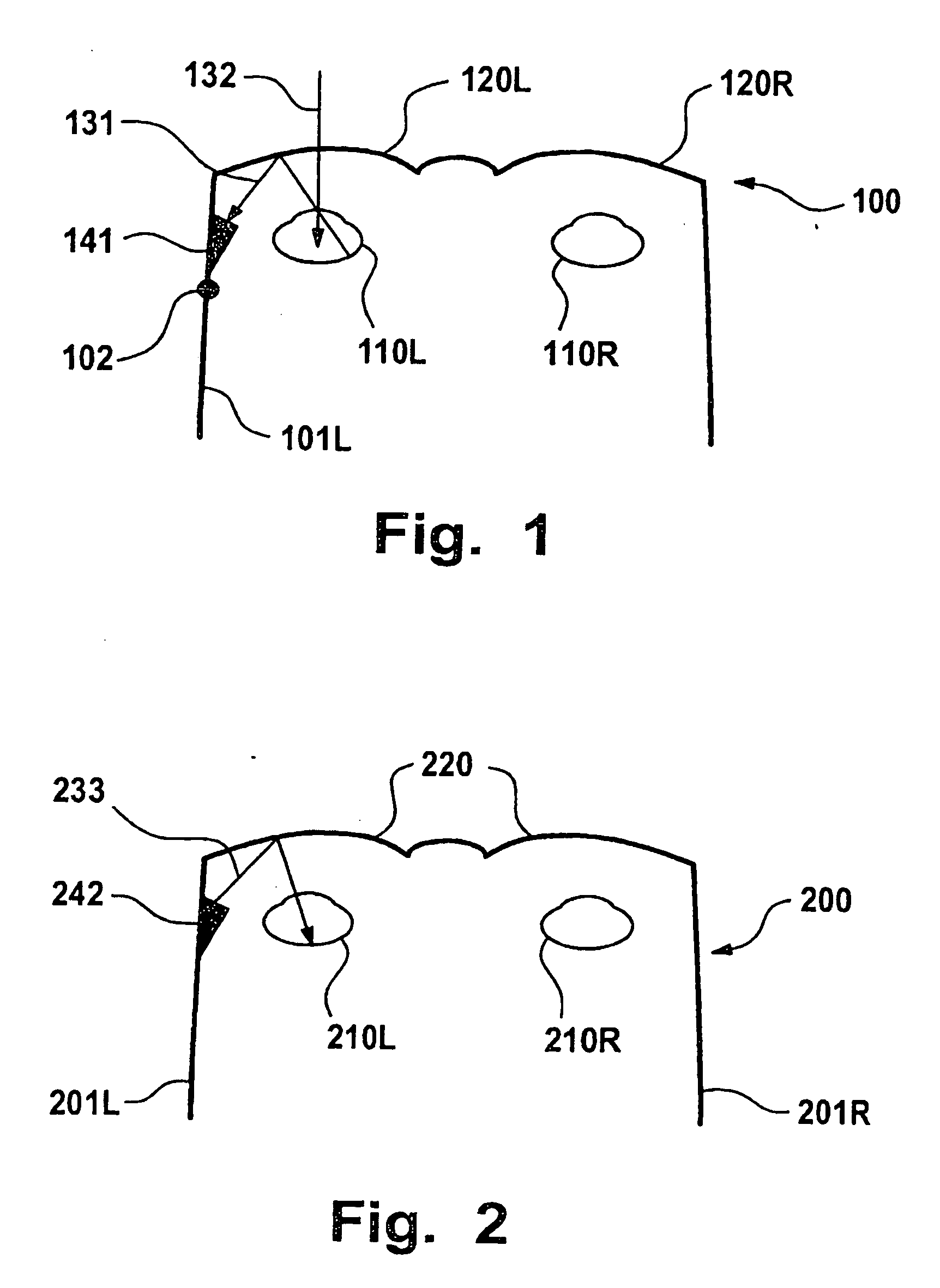
Information system for providing information in correlation with light incident on an eye, having a holographic element disposed in front of the eye, and an
optical scanning device which detects light incident on the eye by way of the holographic element. 2.
Information system according to Point 1, wherein the
optical scanning device is at a fixed predetermined angular ratio with respect to the holographic element. 3.
Information system according to Point 1 or 2, wherein the
optical scanning device detects light which is refracted by the holographic element before it impinges on the eye and does not enter the eye. 4. Information
system according to one of the preceding points, wherein the optical scanning device detects light which was first reflected back from the eye and was then refracted by the holographic element. 5. Information
system according to one of the preceding points, wherein the holographic element refracts light originating from the field of vision of the eye only at several discrete wavelengths in the
visible range before the light impinges on the eye for the detection by the optical scanning device, and refracts light reflected back from the eye only at one discrete
wavelength in the
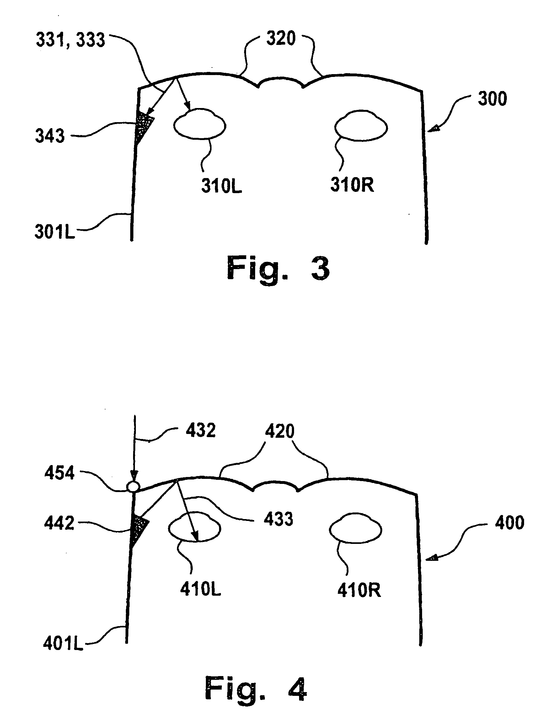
infrared range for the detection by the optical scanning device. 6. Information
system according to one of the preceding points, wherein the holographic element refracts light originating from the field of vision of the eye at fewer than 20, fewer than 10 or fewer than 5 discrete wavelengths in the
visible range either before the light impinges on the eye or after its backscattering as a result of the eye for the detection by the optical scanning device. 7. Information system according to one of the preceding points, wherein the holographic element refracts light originating from the field of vision of the eye at a discrete
wavelength in the
infrared range either before the light impinges on the eye or after its backscattering as a result of the eye for the detection by the optical scanning device. 8. Information system according to one of the preceding points, wherein the holographic element refracts light reflected back by the eye only at a discrete
wavelength in the
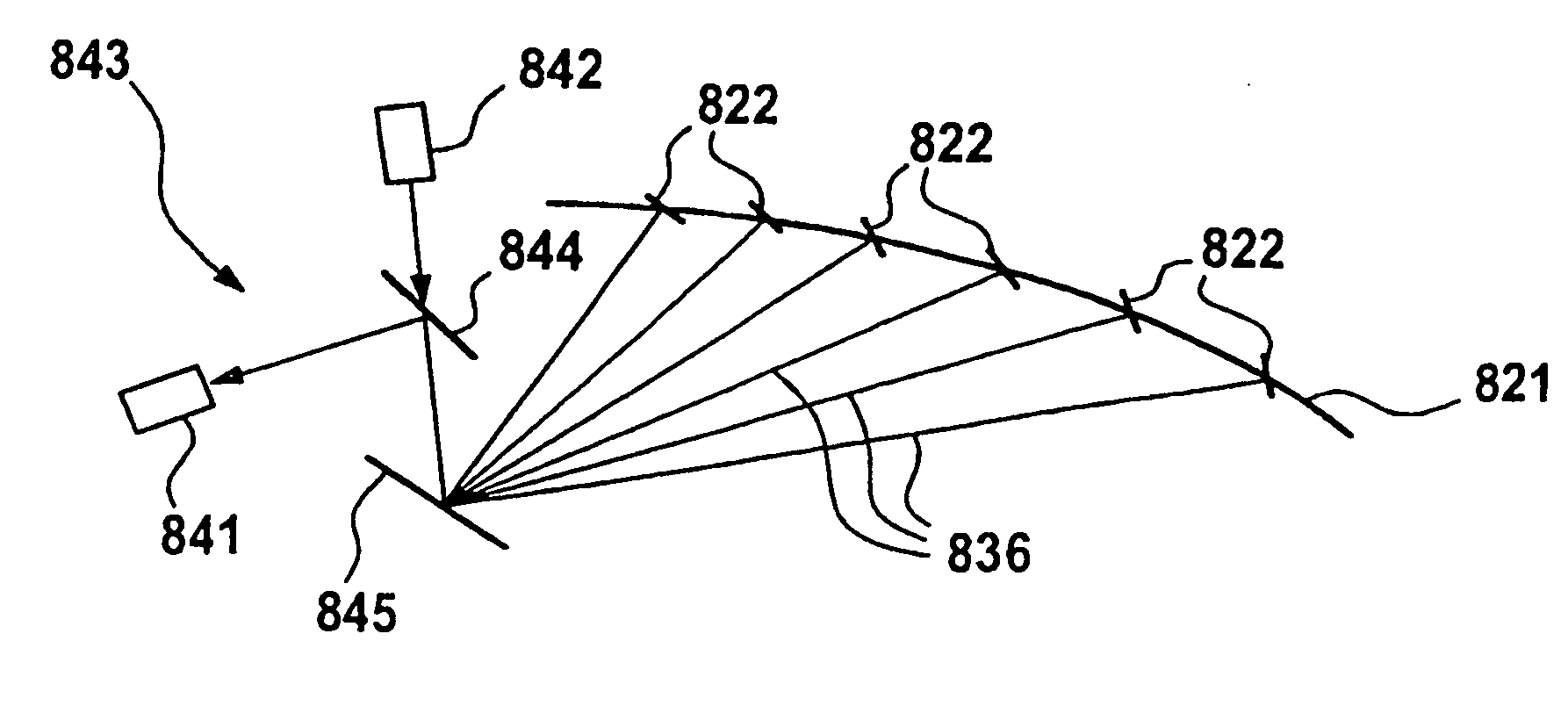
infrared range for the detection by the optical scanning device. 9. Information system according to one of the preceding points, wherein the holographic element refracts light of one or several discrete wavelengths, at which the optical scanning device has a high sensitivity. 10. Information system according to one of the preceding points, wherein the holographic element refracts light a several discrete wavelengths such that the refracted light is guided to a
common point, and the
angle of incidence of the light on this point permits a clear optionally also wavelength-independent conclusion on the
angle of incidence of the light upon the holographic element. 11. Information system according to one of the preceding points, having an optical projection device which projects light into the eye by way of the holographic element. 12. Information system according to Point 11, wherein the light detected by the optical detection device and the light projected in front of the optical projection device run in the opposite direction through a common light guiding lens system and can be focused such by the optical scanning device or projection device that their respective beams describe the same path from or into the eye. 13. Information system for providing information in correlation with information obtained from an eye, having a holographic element disposed in front of the eye, and an optical projection device which projects light into the eye by way of the holographic element. 14. Information system according to one of Points 11 to 13, wherein the optical projection device projects light only at one or several discrete wavelengths in the
visible range and / or at a wavelength in the infrared range. 15. Information system according to one of Points 11 to 14, wherein the holographic element refracts the wavelengths of the projected light. 16. Information system according to one of Points 11-15, wherein the optical projection device is in a fixed predetermined angular ratio with respect to the holographic element. 17. Information system according to Point 16, wherein the holographic element comprises one or more optical flags, whose
light reflection characteristics can be used by the
information system by means of a
photodetector for calibrating a
projection angle of the optical projection device and / or a light guiding device. 18. Information system according to Point 17, including Point 12, wherein the
information system uses the
light reflection characteristics of the optical flags for calibrating a scanning angle of the optical scanning device and / or a light guiding device. 19. Information system according to Point 17, wherein the optical flags are generated in that reflecting elements are imaged during the creating of the holographic element such in the holographic element that they (something is missing) reflect light of one or several wavelengths which, corresponding to the predetermined angular ratio with respect to the optical projection device is incident on the holographic element, back along the path of incidence. 20. Information system according to Point 19, wherein the
photodetector device has a splitter mirror which is arranged such in the
light beam of the optical projection device that it guides a portion of the light, which impinges on the splitter mirror against the
projection direction, in the direction of a
photodetector which detects in at least two areas situated concentrically around one another. 21. Information system according to one of the preceding points, wherein the holographic element has light-refracting characteristics at one or several discrete wavelengths, which correspond to a reflection on the
concave side of an area constructed according to the curvature of a rotationally symmetrical
ellipsoid. 22. Information system according to one of the preceding points, wherein the holographic element has light refracting characteristics at one or several discrete wavelengths, which correspond to a
refraction on the
concave side of an area constructed according to the curvature of a rotationally symmetrical
ellipsoid, which
refraction corresponds to a reflection on a respective
conical surface which is rotationally symmetrical about the axis of rotation of the
ellipsoid and is perpendicular with respect to the ellipsoid at the site of the
refraction. 23. Method of providing information in correlation with light incident on an eye, whereby a holographic element is disposed in front of the eye, and an optical scanning device detects the light incident on the eye by means of the holographic element. 24. Method according to Point 23, whereby the optical scanning device is at a fixed predetermined angular ratio with respect to the holographic element. 25. Method according to Point 23 or 24, whereby the optical scanning device detects light which is refracted by the holographic element before impinging on the eye and does not enter the eye. 26. Method according to one of Points 23 to 25, whereby the optical scanning device detects light which was first reflected back from the eye and was then refracted by the holographic element. 27. Method according to one of Points 23 to 26, whereby the holographic element refracts light originating from the field of vision of the eye only at several discrete wavelengths in the visible range before its impinging on the eye for the detection by the optical scanning device and refracts light reflected back from the eye only at a discrete wavelength in the infrared range for the detection by the optical scanning device. 28. Method according to one of Points 23 to 27, whereby the holographic element refracts light originating from the field of vision of the eye at fewer than 20, fewer than 10 or fewer than 5 discrete wavelengths in the visible range either before its impinging on the eye or after its backscattering as a result of the eye for the detection by the optical scanning device. 29. Method according to one of Points 23 to 28, whereby the holographic element refracts light originating from the visual field of the eye at a discrete wavelength in the infrared range either before its impinging on the eye or after its backscattering as a result of the eye for the detection by the optical scanning device. 30. Method according to one of Points 23 to 29, whereby the holographic element refracts light reflected back from the eye only at a discrete wavelength in the infrared range for the detection by the optical scanning device. 31. Method according to one of Points 23 to 30, whereby the holographic element refracts light of one or several discrete wavelengths, at which the optical scanning device has a high sensitivity. 32. Method according to one of Points 23 to 31, whereby the holographic element refracts light at several discrete wavelengths such that the refracted light is guided to a
common point, an the
angle of incidence of the light onto this point allows a clear, optionally also wavelength-independent conclusion on the angle of incidence of the light upon the holographic element. 33. Method according to one of Points 23 to 32, whereby an optical projection device projects light by way of the holographic element into the eye. 34. Method according to Point 33, whereby the light detected by the optical scanning device and the light projected in front of the optical projection device run in the opposite direction through a common light guiding lens system and can be focused such by the optical scanning device or projection device that their respective beams describe the same path from or into the eye. 35. Method of providing information in correlation with information obtained from an eye, whereby a holographic element is disposed in front of the eye, and an optical projection device projects light by way of the holographic element into the eye. 36. Method according to points 33 to 35, whereby the optical projection device projects light only at one or several discrete wavelengths in the visible range and / or at a wavelength in the infrared range. 37. Method according to one of Points 33 to 36, whereby the holographic element refracts the wavelengths of the projected light. 38. Method according to one of Points 33 to 37, whereby the optical projection device is in a fixed predetermined angular ratio with respect to the holographic element. 39. Method according to Point 38, whereby the holographic element is equipped with one or more optical flags, whose
light reflection characteristics can be used by means of a photodetector device for calibrating a
projection angle of the optical projection device and / or a light guiding device. 40. Method according to Point 39, including Point 34, whereby the light reflection characteristics of the optical flags are used for calibrating a scanning angle of the optical scanning device and / or a light guiding device. 41. Method according to Point 39, whereby the optical flags are generated in that reflecting elements are imaged during the creating of the holographic element such in the holographic element that they beam light of one or more wavelengths which, corresponding to the predetermined angular ratio with respect to the optical projection device is incident on the holographic element, back along the incidence path. 42. Method according to Point 41, whereby the photodetector device is equipped with a photodetector detecting in at least two areas situated concentrically around one another, and a splitter mirror which is arranged such in the
light beam of the optical projection device that it directs a portion of the light impinging on the splitter mirror against the projecting direction, in the direction of the photodetector. 43. Method according to one of Points 23 to 42, whereby the holographic element has light-refracting characteristics at one or several discrete wavelengths which correspond to a reflection on the
concave side of an area constructed according to a curvature of a rotationally symmetrical ellipsoid. 44. Method according to one of Points 23 to 43, whereby the holographic element has light-refracting characteristics at one or several discrete wavelengths, which correspond to a refraction on the concave side of an area constructed according to a curvature of a rotationally symmetrical ellipsoid, which refraction corresponds to a reflection on a respective
conical surface rotationally symmetrical about the axis of rotation of the ellipsoid, which
conical surface is perpendicular with respect to the ellipsoid at the site of the refraction. While the preceding description with respect to the title is limited to embodiments falling under the initially mentioned generic terms “scanning
information system” and “projecting information system”, each individual discussed characteristic of their disclosure can also be used in an embodiment of the systems, devices and methods initially identified by reference to their full content. The applications by the same applicant and / or the same inventors mentioned in the present application should be considered to be a correlated invention complex.

