
Surgical instrument

a surgical instrument and adhesive technology, applied in the field of surgical instruments, can solve the problems of undesired alteration of the shape of the transition area, inability of the adhesive to evaporate, etc., and achieve the effect of increasing the adhesive strength

Active Publication Date: 2008-09-09
AESCULAP AG
View PDF21 Cites 79 Cited by
  • Summary
  • Abstract
  • Description
  • Claims
  • Application Information

AI Technical Summary

Benefits of technology

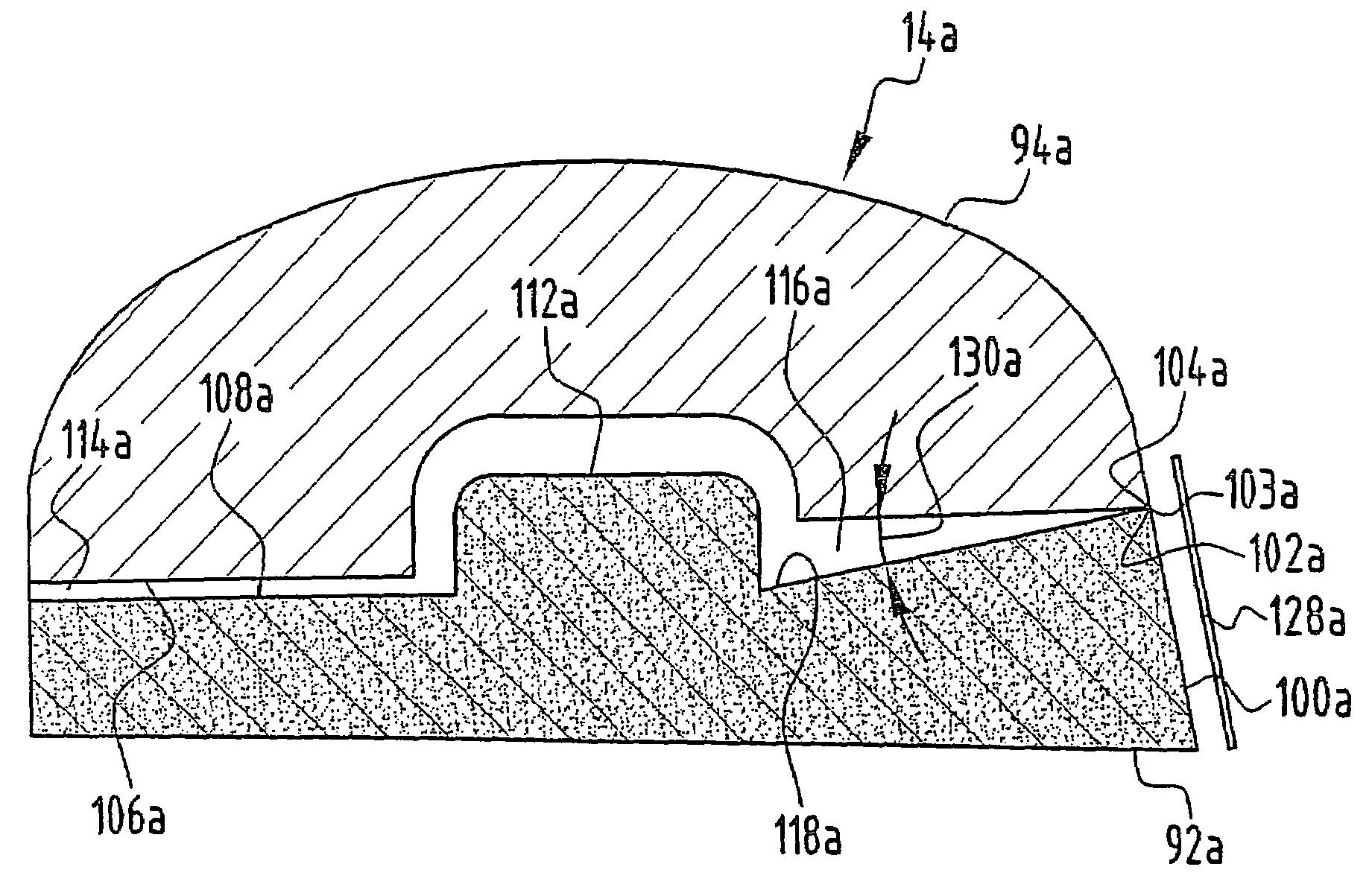
[0006]With carrier and functional component designed accordingly, such a construction has the advantage that a defined coagulation path is formed along the area of transition between the carrier and the functional component, for example, between a metal and a ceramic material, when the instrument is used as bipolar instrument. Furthermore, when current is passed along the contact surfaces, evaporation of an adhesive cannot occur because adhesive cannot get in between the contact surfaces in this area during the bonding owing to the two contact surfaces bearing on each other without any gap between them.
[0024]To increase the adhesive strength it is advantageous for the surface of the first and / or the second adhesive surface to be larger than a projection of the first and / or the second adhesive surface onto the respective other adhesive surface. Such a configuration ensures that the adhesive surface, as a whole, is enlarged, which increases a surface of application for the adhesive.

Problems solved by technology

Furthermore, when current is passed along the contact surfaces, evaporation of an adhesive cannot occur because adhesive cannot get in between the contact surfaces in this area during the bonding owing to the two contact surfaces bearing on each other without any gap between them.
It is thus impossible for the adhesive to evaporate when current is passed over the tool.
In particular, no bonding agent, for example, in the form of an adhesive or any other bonding material, such as, for example, soldering tin, can leak in the area of transition between the carrier and the functional component and thereby alter the shape of the area of transition in an undesired manner.

Method used


Image

  • Surgical instrument
  • Surgical instrument
  • Surgical instrument

Examples


Embodiment Construction

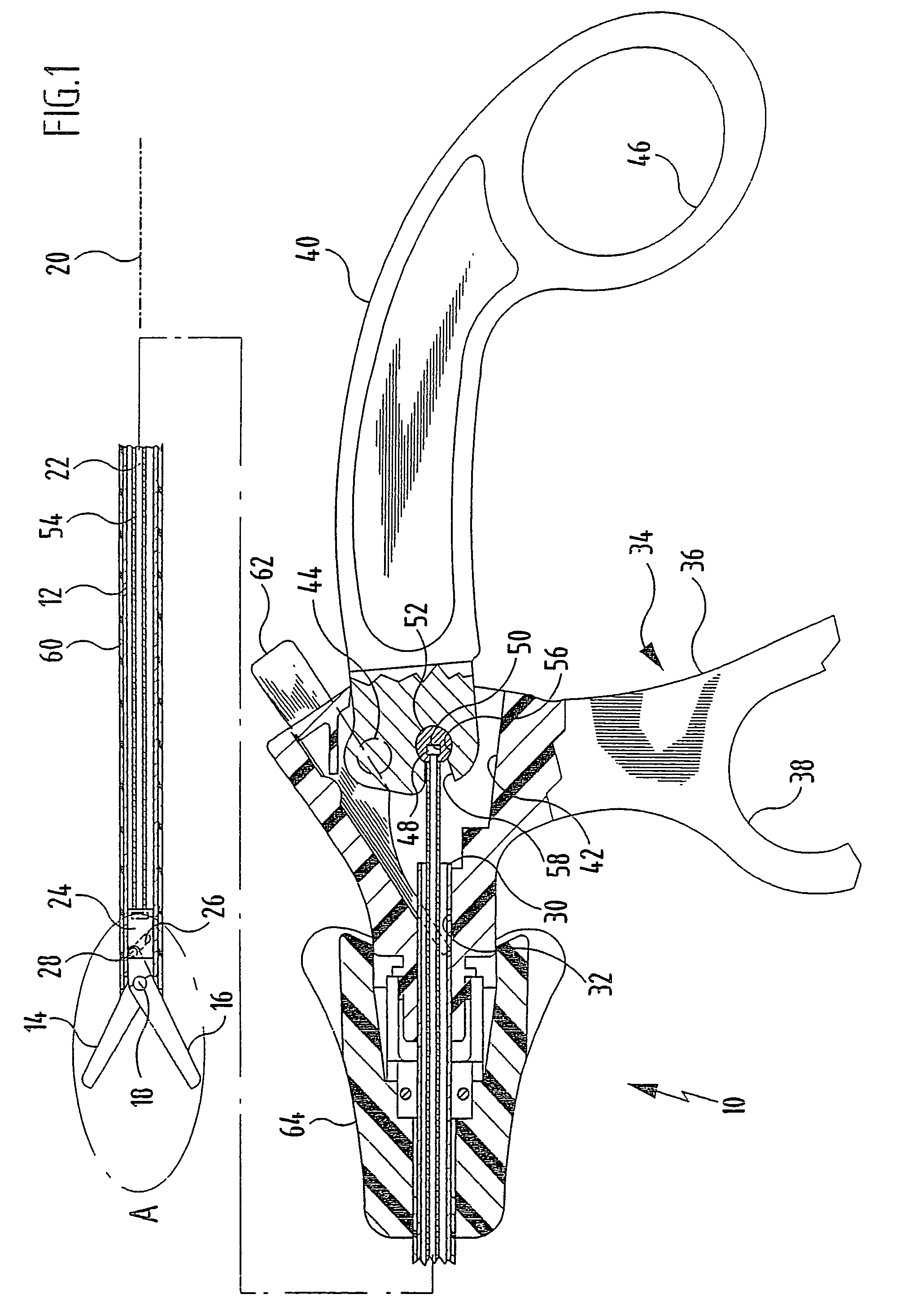
[0040]A longitudinal sectional view of bipolar scissors generally designated by the reference numeral 10, constructed as an endoscopic tubular shaft instrument, is shown in FIG. 1.

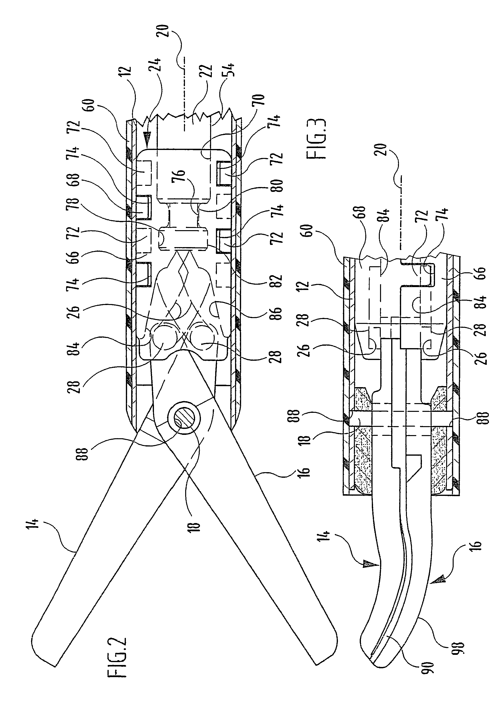
[0041]The bipolar scissors 10 comprise an elongated, tubular shaft 12, at the distal end of which two scissor blades 14 and 16 pivotable relative to each other are mounted on a bearing pin 18 which extends through the shaft 12 on either side thereof and transversely to a longitudinal axis 20 of the shaft 12.

[0042]For moving the scissor blades 14 and 16 a drive member 24 is arranged at a distal end of a push-and-pull rod 22 which is longitudinally displaceable in the direction of the longitudinal axis 20 in the shaft 12. The drive member 24 is provided with two guide slots 26 in which bearing pins 28 projecting from the scissor blades 14 and 16 transversely to the longitudinal axis 20 engage and are guided as a result of an axial displacement of the drive member 24, whereby the scissor blades 14 and 16 are ...


PUM


Abstract

In order to improve a surgical instrument having at least one tool comprising a carrier and at least one functional component adhesively bonded to the carrier, in such a way that the carrier can be easily and securely adhesively bonded to the functional component, whilst maintaining the desired function of the instrument, it is proposed that the carrier comprise a first contact surface, that the functional component comprise a second contact surface, and that the first contact surface bear on the second contact surface without any gap therebetween.

Description

[0001]The present disclosure relates to the subject matter disclosed in German application No. 103 28 512.1 of Jun. 20, 2003, which is incorporated herein by reference in its entirety and for all purposes.BACKGROUND OF THE INVENTION[0002]The present invention relates to a surgical instrument with at least one tool comprising a carrier and at least one functional component adhesively bonded to the carrier.[0003]Surgical instruments of the kind described at the outset are known, for example, in the form of scissors comprising a metallic or plastic scissor blade to which a ceramic or metal cutter is adhesively bonded. Such a two-part construction of the tool is used, for example, in bipolar instruments, as such instruments require tools which are electrically insulated from one another. When current is passed over the tool during use of the instrument, this may cause evaporation of the adhesive along the cutting edge.[0004]The object of the present invention is, therefore, to so improv...

Claims


Application Information

Patent Timeline
Patent Type & Authority Patents(United States)
IPC IPC(8): A61B18/18A61B17/32A61B17/28A61B18/12A61B18/14
CPCA61B18/1445A61B17/320016A61B2018/1432A61B2017/2945A61B2017/292
Inventor KUPFERSCHMID, BERNHARDMAYENBERGER, RUPERTWEISSHAUPT, DIETER
Owner AESCULAP AG
Learn More