Eureka AIR delivers breakthrough ideas for toughest innovation challenges, trusted by R&D personnel around the world.

Collet-type splice and dead end use with an aluminum conductor composite core reinforced cable

a technology of composite core and splice, which is applied in the direction of cable termination, connection contact member material, synthetic resin layered products, etc., can solve the problems of compressive force and enormous friction bond between the collet, and the methods and systems for installing these cables have yet to be created, so as to achieve good mechanical and electrical junction, increase compressive force

Inactive Publication Date: 2006-03-28
CTC GLOBAL CORP
View PDF6 Cites 72 Cited by
  • Summary
  • Abstract
  • Description
  • Claims
  • Application Information

AI Technical Summary

Benefits of technology

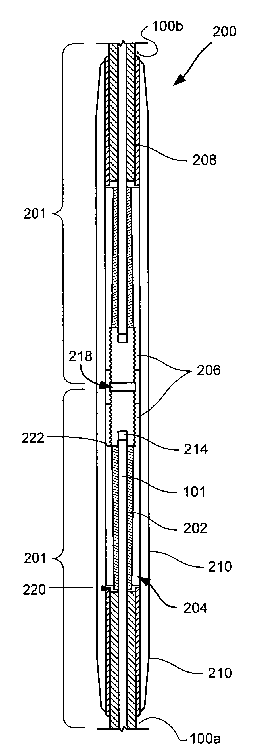
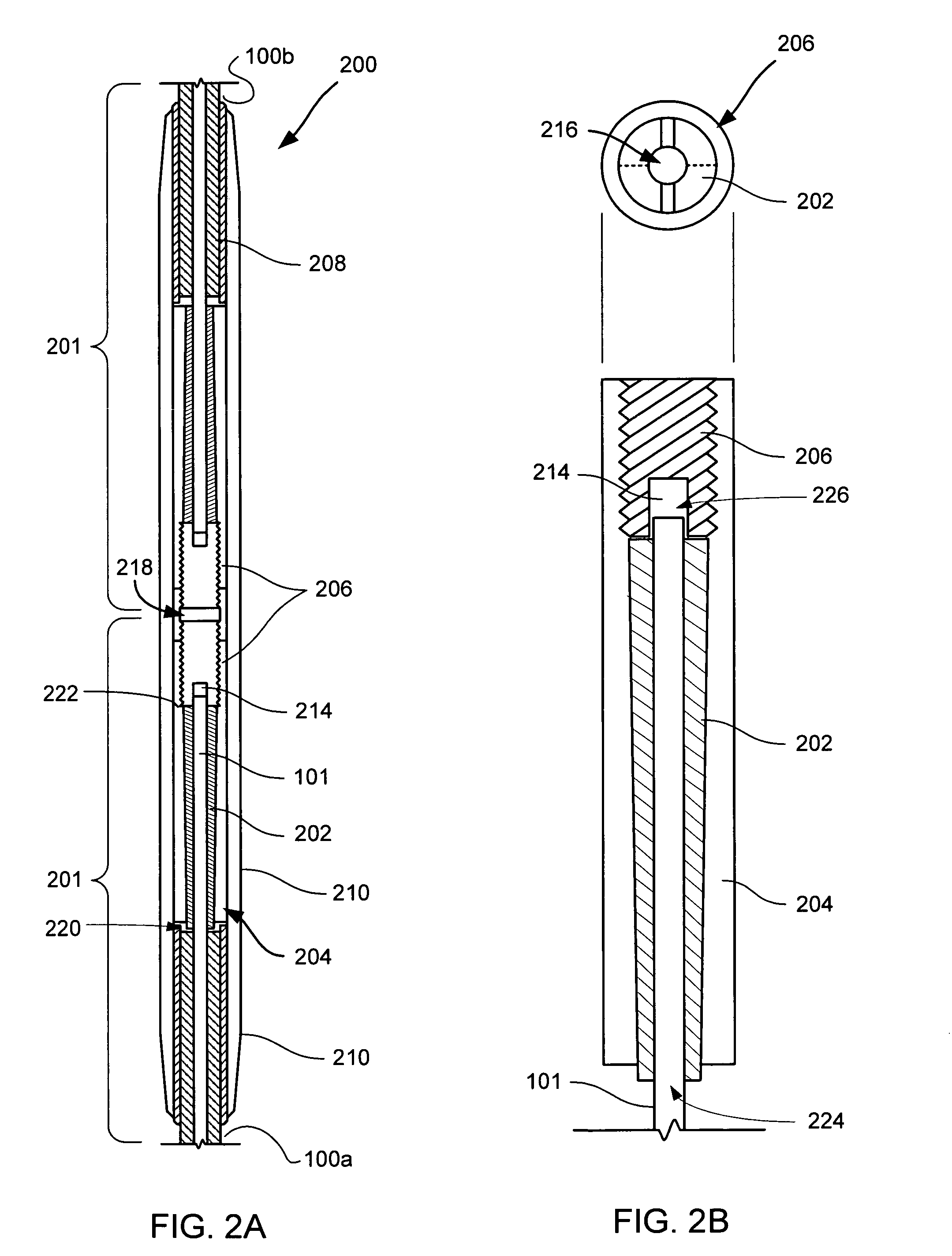
[0016]A collet-type fitting uses a collet inside a collet housing to hold the composite cores. The composite core cables can be stripped of the aluminum conductor to provide the best bond between the collet and the composite core, which is the load-bearing member of the cable. After inserting the composite core into the collet, a compression implement may be used to compress the collet against the composite core. The shape of the collet housing forces the collet to increase the compressive force as it moves further into the collet housing. These compressive forces create enormous friction bond between the collet and the composite core. The friction bond holds the composite core to the collet. The compression fitting can be covered by an aluminum housing to transfer the electric current over the splice. This compression fitting enables a good mechanical and electrical junction.

Problems solved by technology

Unfortunately, methods and systems to install these cables have yet to be created.
These compressive forces create enormous friction bond between the collet and the composite core.

Method used


Image

  • Collet-type splice and dead end use with an aluminum conductor composite core reinforced cable
  • Collet-type splice and dead end use with an aluminum conductor composite core reinforced cable
  • Collet-type splice and dead end use with an aluminum conductor composite core reinforced cable

Examples


Embodiment Construction

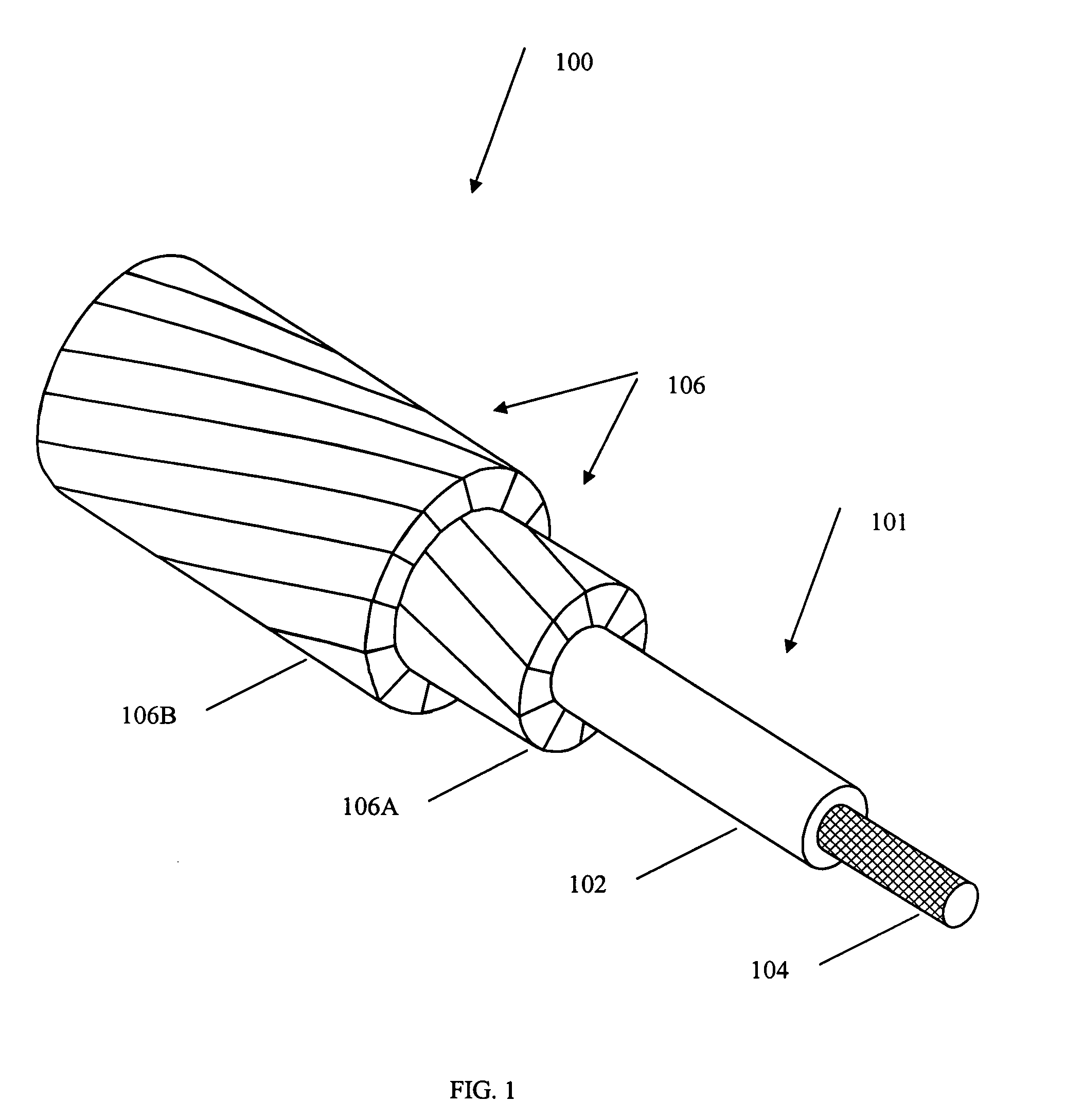
[0025]The present invention will now be described more fully hereinafter with reference to the accompanying drawings, in which exemplary embodiments of the invention are shown. This invention may, however, be embodied in many different forms and should not be construed as limited to the embodiments set forth herein. Rather, these embodiments are provided so that the disclosure will fully convey the scope of the invention to those skilled in the art. The drawings are not necessarily drawn to scale but are configured to clearly illustrate the invention. The invention is as set forth in the claims. Throughout this description, the term “couple”, “couples”, or “coupled” means any type of physical attachment or connection of two parts.

[0026]The present invention relates to methods and apparatuses to splice together two composite core 101 reinforced cables. FIG. 1 illustrates one embodiment of an ACCC reinforced cable 100. FIG. 1 illustrates an ACCC reinforced cable 100 having a reinforce...


PUM

PropertyMeasurementUnit
lengthsaaaaaaaaaa
lengthsaaaaaaaaaa
diameteraaaaaaaaaa

Abstract

This invention relates to collet-type splices and collet-type dead ends and methods for splicing together two aluminum conductor composite core reinforced cables (ACCC) or terminating one ACCC cable. The collet-type fittings use a collet inside a collet housing to hold the composite cores. The composite cores can be stripped of the aluminum conductor to provide a bond between the collet and the composite core. After inserting the composite core into the collet, a compression implement compresses the collet. The collet holds the composite core with frictional forces and the collet further compresses and strengthens the hold on the composite core if the composite core pulls the collet further into the collet housing.

Description

CROSS REFERENCES TO RELATED APPLICATIONS[0001]In relation to this Continuation in Part Application, applicants claim priority of earlier U.S. CIP application Ser. No. 10 / 690,839 filed in the United States Patent and Trademark Office on 22 Oct. 2003, which is incorporated by reference herein and which is a continuation in part of and claims priority from earlier PCT filing PCT / US03 / 12520 filed in the International Receiving Office of the United States patent and Trademark Office on 23 Apr. 2003, the entire disclosure of which is incorporated by reference herein, which claims priority from U.S. provisional application Ser. No. 60 / 374,879 filed in the United States patent and Trademark Office on 23 Apr. 2002, the entire disclosure of which is incorporated by reference herein.STATEMENT REGARDING FEDERALLY SPONSORED RESEARCH OR DEVELOPMENT[0002]Not ApplicableREFERENCE TO A “MICROFICHE APPENDIX”[0003]Not ApplicableBACKGROUND OF THE INVENTION[0004]1. Field of the Invention[0005]The present...

Claims


Application Information

Patent Timeline
Patent Type & Authority Patents(United States)
IPC IPC(8): H02G3/06B32B5/02B32B27/04B32B27/12H01RH01R4/50H01R4/62
CPCH01R4/5083H01R4/62H02G7/04H02G15/18H02G15/06H02G15/10H02G7/056H01R4/50
Inventor BRYANT, DAVID
Owner CTC GLOBAL CORP
Why Eureka
Eureka Blog
Learn More