Bone plate

a bone plate and bone plate technology, applied in the field of bone plate fixation devices, can solve the problems of poor clinical and limited surgeons, and achieve the effect of not compromising strength, size and integrity of bone plates

Active Publication Date: 2010-08-17
SYNTHES USA
View PDF77 Cites 143 Cited by
  • Summary
  • Abstract
  • Description
  • Claims
  • Application Information

AI Technical Summary

Benefits of technology

[0010]Among the various different types of bone plate holes that are known in the art are threaded holes and non-threaded holes. “Locking” screws (screws with threaded heads) are typically used with threaded holes. Locking screws, when mated with threaded holes, possess high resistance to shear and torsional forces and therefore ensure stability between the screw and bone plate. “Non-locking” screws are typically used with unthreaded holes and, unlike locking screws that mate with threaded holes, may be inserted at any one of a number of angles. Non-locking screws provide optimal compression of fractured ends.
[0012]It will be appreciated that either type of the aforementioned screws may be used (and produce its intended results) with a coaxial combination hole. The threaded head of a threaded-head screw may mate with threaded middle region of the hole. Alternatively, a screw with an unthreaded head (or even a screw with a threaded head) may be inserted through a coaxial combination hole, without any mating of any threads, at any one of a number of angles. The outward taper of the coaxial combination hole's lower region provides room for the screw's shaft to be inserted at an angle (with respect to the center of the hole). Likewise the curved inward taper of the upper region of the hole provides a seat for the screw head to rest in, even when the screw is inserted at an angle. It will be appreciated, then, that at any given coaxial combination hole, a surgeon may elect to use either a screw for screw-plate stability or a screw for compression of fracture ends.
[0013]Coaxial combination holes may be placed in any type of bone plate. Coaxial combination holes provide multiple options for the surgeon. And because the holes do not require a larger cavity in the bone plate than would otherwise be necessary for an ordinary hole, the strength, size, and integrity of the bone plate are not compromised. Coaxial combination holes are therefore particularly useful in relatively small bone plates (e.g., pubic symphysis plates).

Problems solved by technology

This can lead to malalignment and poor clinical results.
Surgeons are limited, however, by the manufacturers' placement of the varying holes on a given bone plate.

Method used


Image

  • Bone plate
  • Bone plate
  • Bone plate

Examples


Embodiment Construction

[0038]The present invention is described below with reference to the preferred embodiments. Those skilled in the art will recognize that numerous variations and modifications may be made without departing from the scope of the present invention. Accordingly, it should be understood that the embodiments of the invention described below are not intended as limitations on the scope of the invention, which is defined only by the claims.

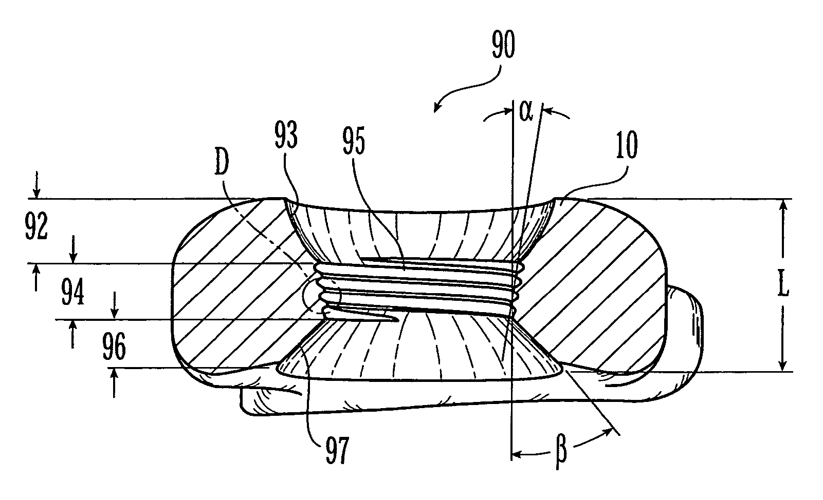
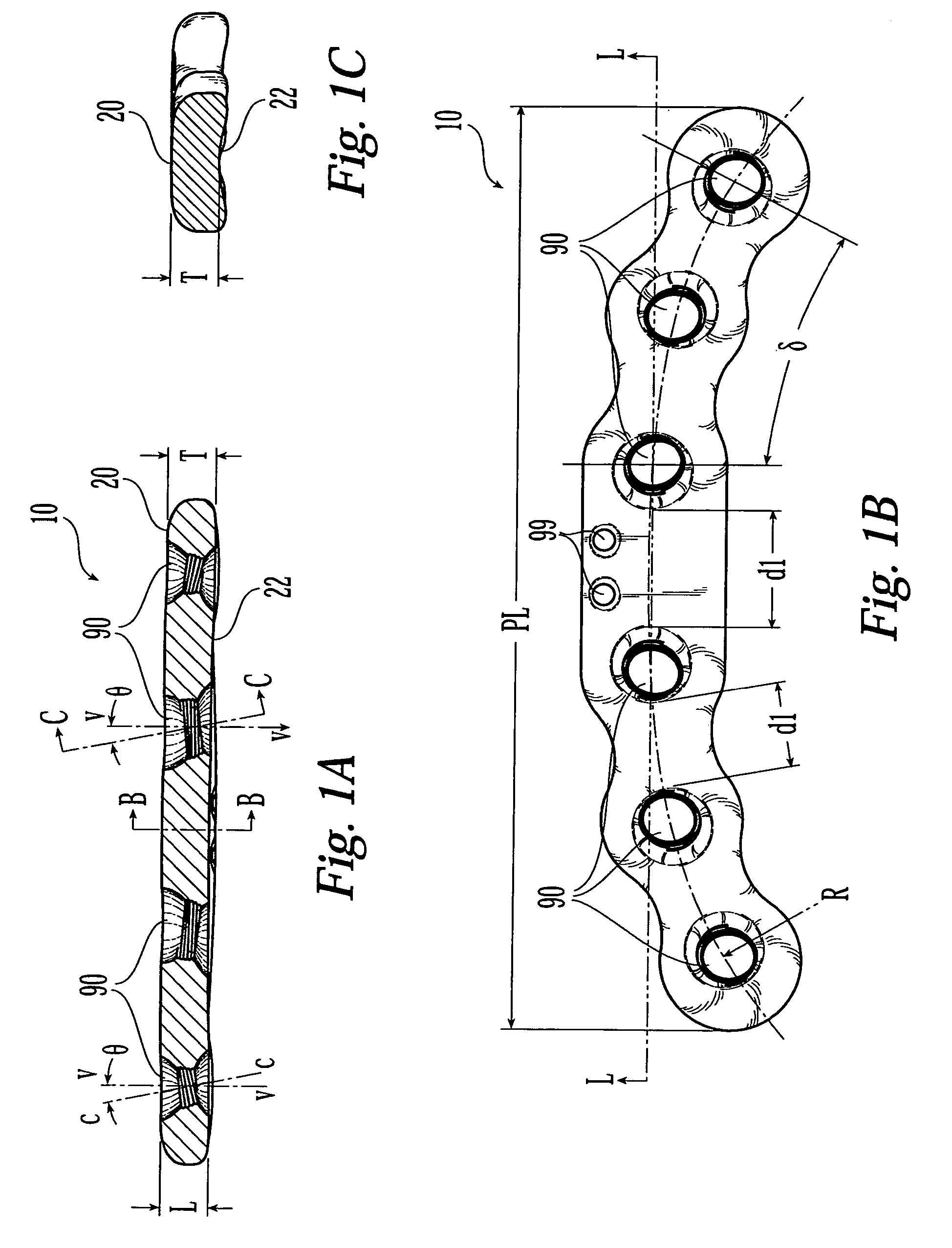
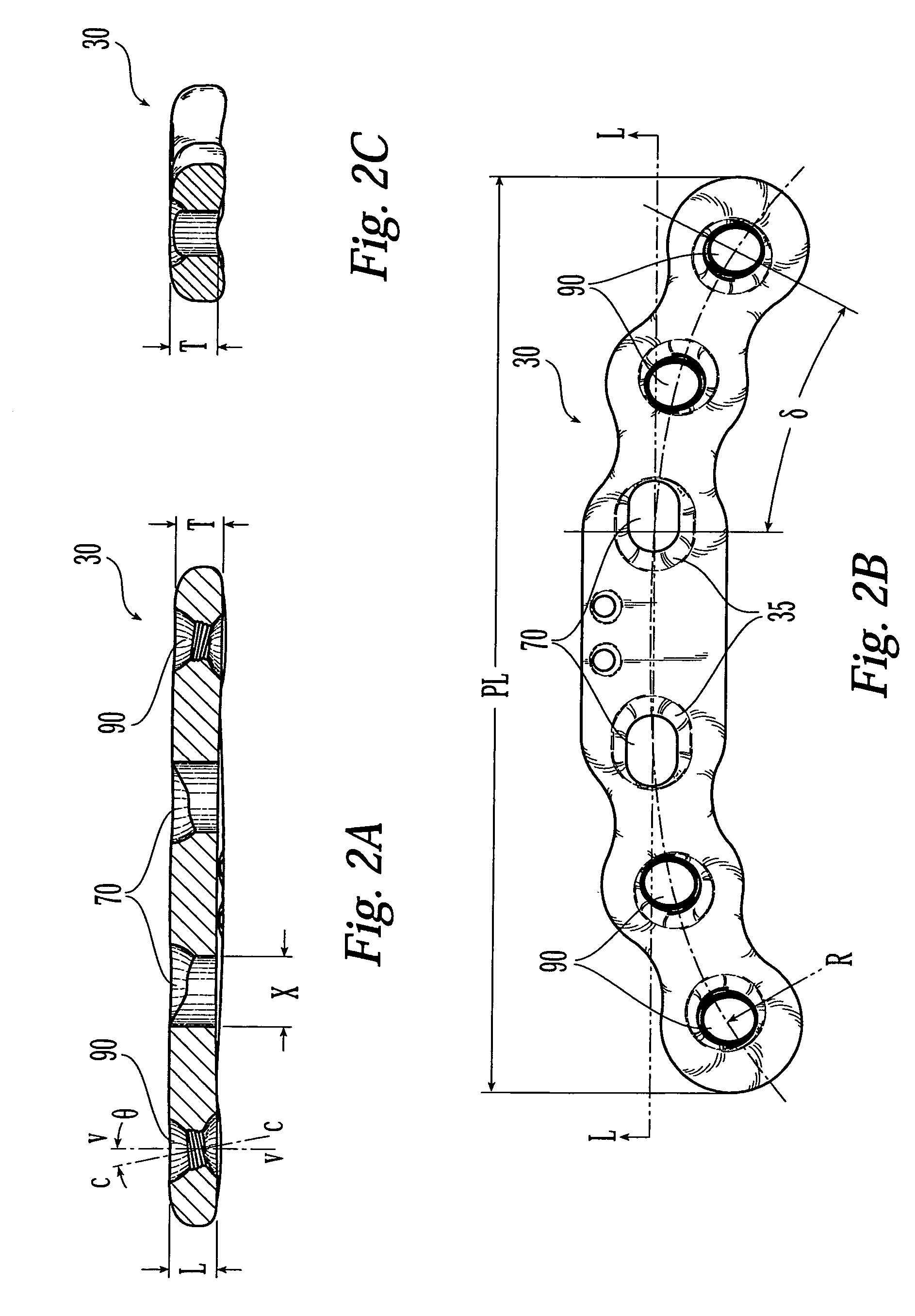
[0039]Reference is now made to FIGS. 1A, 2A, and 3A, which illustrate side, cross-sectional views of various embodiments of a bone plate. The bone plates may have at least one coaxial combination hole 90, which has a length L that extends from the upper surface of the bone plate to the lower surface of the bone plate. The coaxial combination hole 90 is threaded only partially through the hole's length L. As such, with a given coaxial combination hole, a surgeon may elect to: (1) thread a screw having a thread on at least a portion of its head into and thr...


PUM


Abstract

A bone plate has an upper surface, a lower surface, and at least one first hole extending through the upper and lower surfaces. The first hole has two or three vertically separate regions, each region communicating with or abutting an adjacent region. The first hole has a first unthreaded upper region, which has a curved inward taper from the plate's upper surface toward the plate's lower surface. The first hole has a second threaded middle region, which has a conical inward taper from the plate's upper surface toward the plate's lower surface. A third unthreaded lower region has a conical outward taper from the plate's upper surface toward the plate's lower surface. The bone plate may be straight, curved, or include a combination of both straight and curved segments.

Description

CROSS-REFERENCE TO RELATED APPLICATIONS[0001]The present application is a continuation-in-part of U.S. patent application Ser. No. 10 / 843,113, filed on May 11, 2004, currently pending. The entire contents of this application is expressly incorporated herein by reference thereto.FIELD OF THE INVENTION[0002]The present invention relates generally to devices for bone fracture fixation and more specifically, to bone plates and systems for stabilization and / or compression of bone fractures.BACKGROUND OF THE INVENTION[0003]The use of bone plate and screw systems for treatment of bone fractures is widespread. Conventional bone plate and screw systems promote healing of a fracture by compressing the fracture ends together and drawing the bone fragments into close apposition with each other. If the plate is not provided with the appropriate hole types adapted to receive the proper screw types, then the angular relationships between the plate and screws may change postoperatively. This can le...

Claims


Application Information

Patent Timeline
Patent Type & Authority Patents(United States)
IPC IPC(8): A61B17/80A61B17/56A61B17/58A61F2/30
CPCA61B17/8014A61B17/8057A61B17/8066A61B17/58A61B17/82A61B17/80
Inventor GRADY, JR., MARK P.MAYO, KEITH A.MAST, JEFF W.BOLHOFNER, BRETT R.KOAY, KENNY
Owner SYNTHES USA
Why Eureka
Try Eureka