Umbrella rib connector

a technology of ribs and connectors, applied in the direction of walking sticks, etc., can solve the problems of corroding of exposed rivets with extended use, affecting the appearance of sunshade, and complicated assembly processes, etc., and achieves the effects of convenient assembly, stable positioning, and pleasing appearan

Active Publication Date: 2016-03-01
OLIVER JOEN AN MA
View PDF196 Cites 7 Cited by
  • Summary
  • Abstract
  • Description
  • Claims
  • Application Information

AI Technical Summary

Benefits of technology

[0005]Therefore, an umbrella connecting device that is easy to assemble, stable in positioning, wind resistant, pleasing in appearance, economical and practical, is desired to solve problems and shortcomings, including those mentioned above.
[0006]An objective of this application is to address the shortcomings of prior technology by providing new umbrella connecting devices. The umbrella connecting devices are cleverly and uniquely designed, structurally simple, easy to assemble, stable in positioning, wind resistant, pleasing in appearance, economical and practical, and / or suitable for large-scale application.
[0014]The inner wall of the first clamping arm also can have an inclined surface that extends from the outer edge of the inner wall of the first clamping arm to the accommodating portion. The inclined surface can be tilted towards the inner wall of the second clamping arm. One end of an umbrella pin coupled with a short umbrella rib can easily engage one of the accommodating portions of the second clamping arm and another end of the umbrella pin can be passed along the inclined surface disposed on the first clamping arm. The long umbrella rib is installed at the second part and is securely fixed using fasteners.
[0015]The connecting device is cleverly and uniquely designed, structurally simple, easy to assemble, stable in positioning, wind resistant, pleasing in appearance, economical and practical, and it is suitable for large-scale application.
[0019]In another embodiment, an umbrella connecting device is provided that includes a rib and a connector. The rib has a transverse member that has a length and an elongate body from which the transverse member extends. The connector includes a first arm, a second arm, and a connecting portion. The first arm has an inner wall having a first accommodating portion, e.g., a recess, formed therein. The second arm is positioned opposite to the first arm. The second arm has an inner wall that has a second accommodating portion, e.g., a recess. The connecting portion is located between the first arm and the second arm. The connecting portion connects the first arm and the second arm. In the connector, a space is provided between the first and second arms. The space has a width measured transverse to the inner walls of the first and second arms. The width is less than the length of the transverse member of the rib. The connector is configured such that upon advancement of the transverse member of the rib into engagement with inner portions of the arms, the arms are deflected away from each other. The deflection permits further advancement of the transverse member to the accommodating portions of the first and second arms.

Problems solved by technology

Sunshades are usually used outdoors and the exposed rivet will corrode with extended use.
The use of these rivets also makes the assembly process more complex and mars the appearance of the sunshade.

Method used


Image

  • Umbrella rib connector
  • Umbrella rib connector
  • Umbrella rib connector

Examples


Embodiment Construction

[0030]While the present description sets forth specific details of various embodiments, it will be appreciated that the description is illustrative only and should not be construed in any way as limiting. Furthermore, various applications of such embodiments and modifications thereto, which may occur to those who are skilled in the art, are also encompassed by the general concepts described herein. Each and every feature described herein, and each and every combination of two or more of such features, is included within the scope of the present inventions provided that the features included in such a combination are not mutually inconsistent.

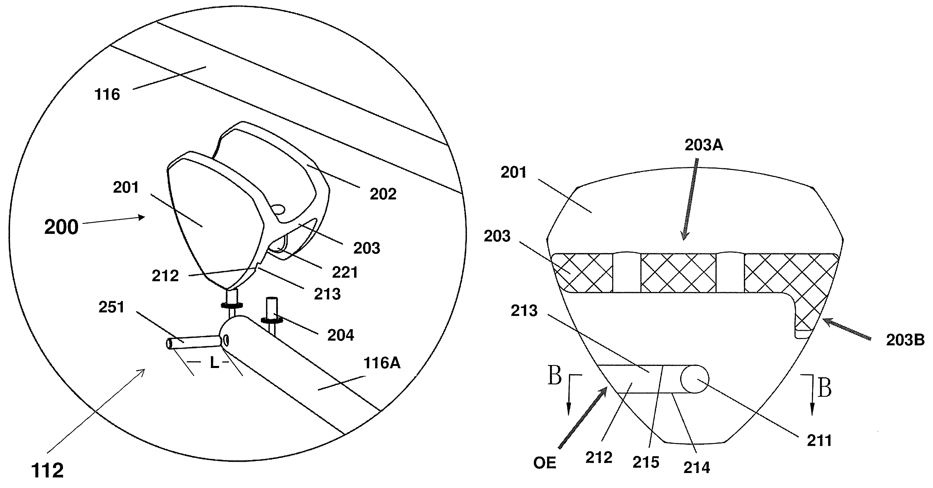
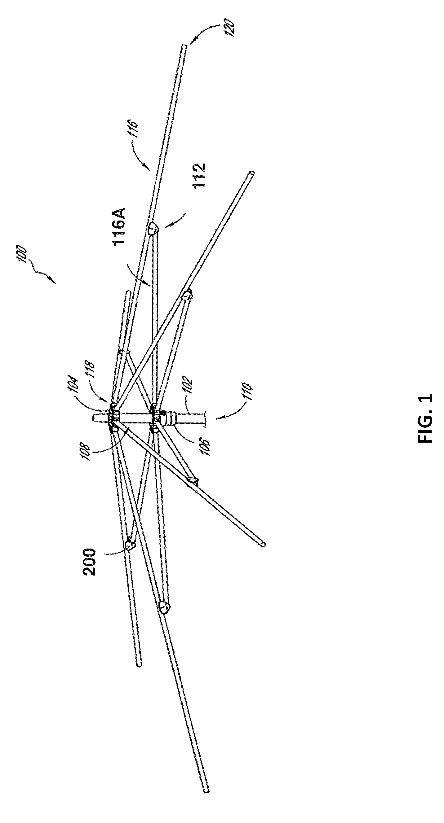
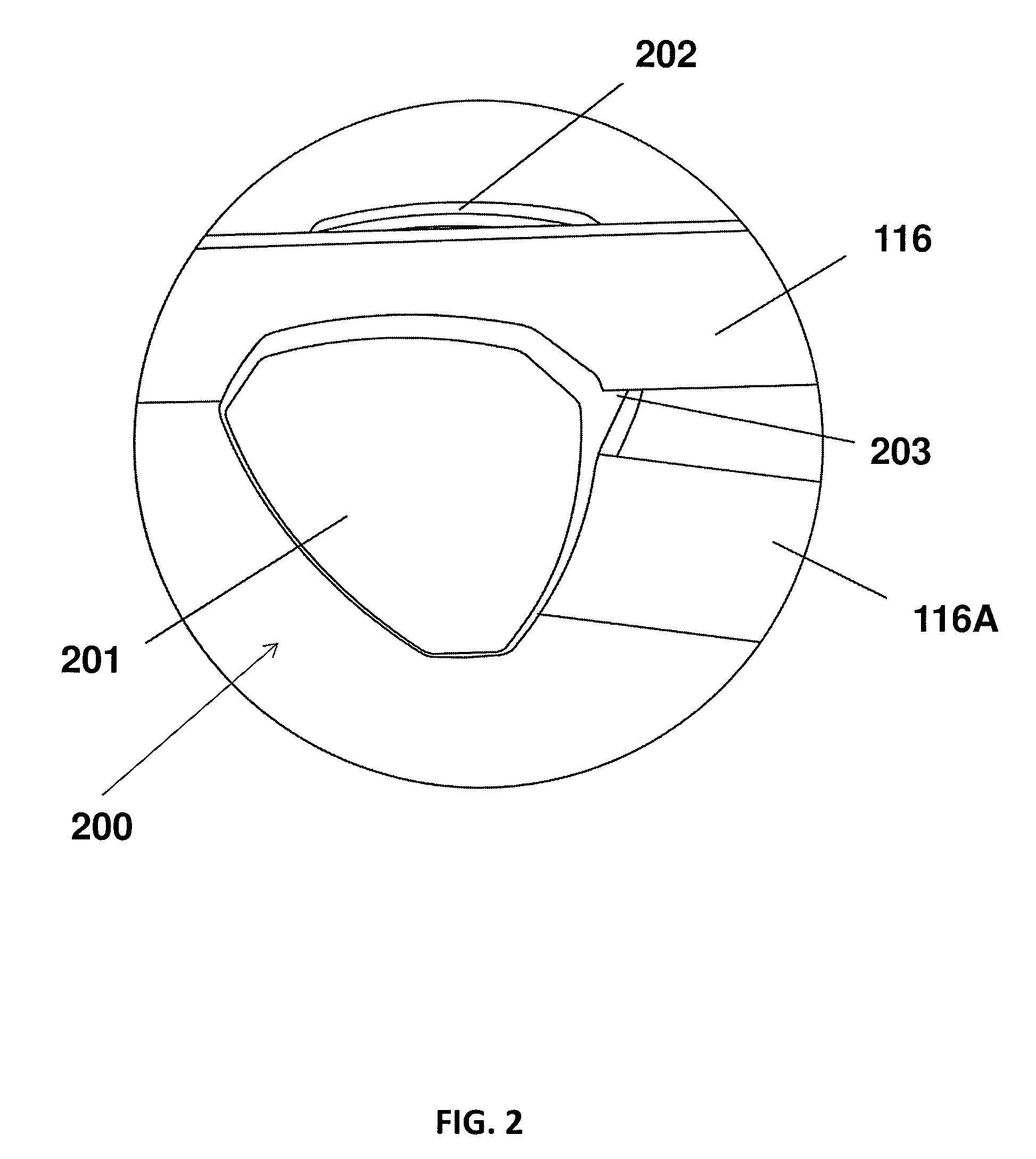
[0031]FIG. 1 illustrates an embodiment of an umbrella or umbrella assembly 100. The umbrella assembly 100 can comprise a pole 102, an upper hub 104, and a lower hub or runner 106. The pole 102 can comprise an upper end 108 and a lower end 110. The upper hub 104 can be configured to be coupled with the upper end 108 of the pole 102. The runner 10...


PUM


Abstract

A rib connector is provided that has a first arm, a second arm, and a transverse member. The first arm has an inner wall, a first recess in the inner wall, and an inclined surface that extends toward the first recess. The second arm has an inner wall and a second recess. The second recess is positioned opposite to the first recess. The transverse member is located between the first arm and the second arm. The transverse member connects the first arm and the second arm. The transverse member is disposed adjacent to a space located between the first and second arms. The space is configured to receive an umbrella rib. A varying distance is provided between the inclined surface and the inner wall of the second arm such that the distance is less at a first position along the inclined surface than at a second position along the inclined surface. The first position is between the first recess and the second position.

Description

BACKGROUND OF THE INVENTION[0001]1. Field of the Invention[0002]This application is directed to connecting devices for components of shelters, including shade structures, pavilions, and umbrellas, which connecting devices are used to connect multiple ribs together, e.g., to connect a short rib and a long rib.[0003]2. Description of the Related Art[0004]A middle disk connecting the long and short umbrella ribs of sunshades available in the current market is fixed at the top of the long umbrella rib. An umbrella pin of the short umbrella rib is installed at the other end of the middle disk. For example Chinese utility model CN99252597.7 describes the use of a rivet to secure the short umbrella rib to a middle disk. In this design, the two ends of the rivet are exposed. Sunshades are usually used outdoors and the exposed rivet will corrode with extended use. The use of these rivets also makes the assembly process more complex and mars the appearance of the sunshade.SUMMARY OF THE INVEN...

Claims


Application Information

Patent Timeline
Patent Type & Authority Patents(United States)
IPC IPC(8): A45B25/02
CPCA45B25/02
Inventor MA, OLIVER, JOEN-AN
Owner OLIVER JOEN AN MA
Why Eureka
Try Eureka