Dynamometer system control device

a control device and dynamometer technology, applied in the direction of measurement devices, instruments, work measurement, etc., to achieve the effect of stable output signal, suppressing the natural vibration of the rocking piece, and stable and highly responsive manner

Active Publication Date: 2016-05-10
MEIDENSHA ELECTRIC MFG CO LTD
View PDF10 Cites 6 Cited by
  • Summary
  • Abstract
  • Description
  • Claims
  • Application Information

AI Technical Summary

Benefits of technology

[0021]According to the present invention, a stable output signal can be obtained from a load cell, without providing an acceleration sensor to a mechanical device. Such a natural-vibration suppression means suppresses the natural vibration of the rocking piece; and as a result, the main control device can control the dynamometer in a stable and highly responsive manner.

Problems solved by technology

In such a structure, in addition to torque which should be actually detected by the dynamometer, a torque fluctuation component is superimposed on an output signal from the load cell, due to natural vibration of the rocking piece; and this fluctuation component is fundamentally unnecessary for the control and measurement of the system.

Method used


Image

  • Dynamometer system control device
  • Dynamometer system control device
  • Dynamometer system control device

Examples


first embodiment

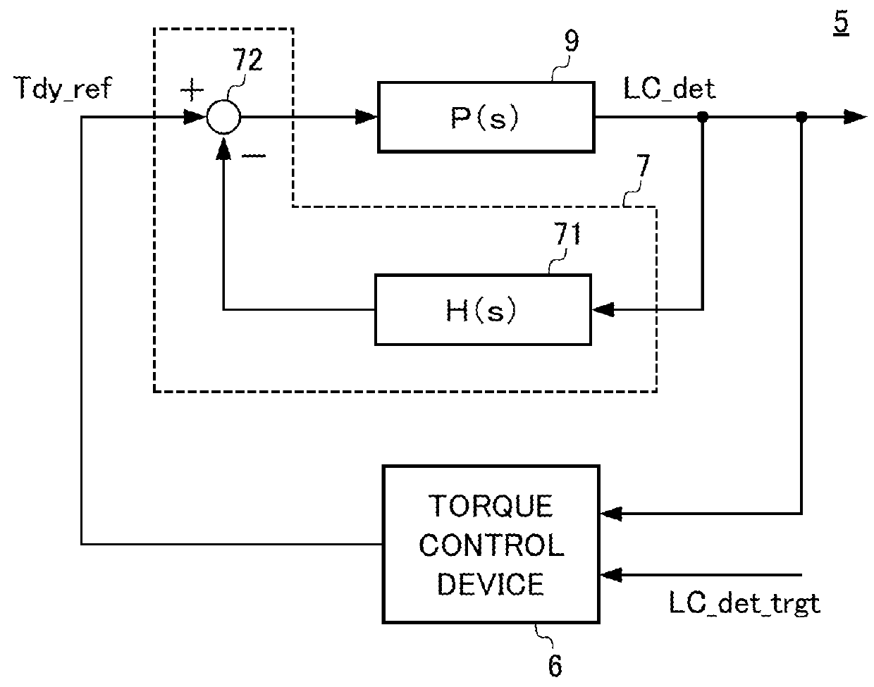
[0053]FIG. 2 is a block diagram showing a configuration of a control device 5 for a dynamometer system of a first embodiment.

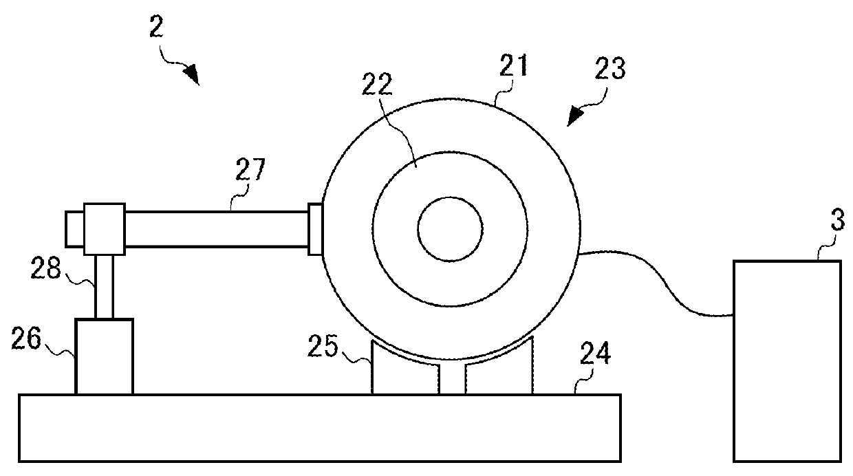
[0054]In FIG. 2, a controlled object 9 is configured by including the inverter, the dynamometer, the load cell, etc. described above with reference to FIG. 1. The control device 5 is provided with: a torque control device 6 as a main control device composing a major loop in the control system shown in FIG. 2; and a natural-vibration suppression circuit 7 composing a minor loop in the control system.

[0055]The torque control device 6 outputs a torque current command signal Tdy_ref, based on inputs such as an output signal LC_det from the load cell, and a target value LC_det_trgt thereof. The main control device is not limited to a control device for controlling torque, but may be replaced with a control device for controlling position, speed, running resistance, etc., as long as the torque current command signal Tdy_ref is output as a control input signal.

[0056]...

second embodiment

[0066]FIG. 5 is a block diagram showing a configuration of a control device 5A for a dynamometer of a second embodiment.

[0067]The control device 5A of the present embodiment is further provided with an observer calculation unit 8A, which is a point of difference from the control device 5 of the first embodiment. In the following descriptions of the control device 5A, identical reference numerals are assigned to configurations which are identical to those of the control device 5 of the first embodiment, and descriptions thereof are omitted.

[0068]The observer calculation unit 8A is provided with a vibration output calculation unit 81A, a delay compensator 82A, and a deviation compensator 83A.

[0069]The vibration output calculation unit 81A outputs an approximation signal Pmdl_det, based on an approximation equation shown in the following Equation (7), by using as an input, a sum of the torque current command signal Tdy_ref′ to be input into the inverter, and a feedback signal (to be de...

third embodiment

[0075]FIG. 6 is a block diagram showing a configuration of a control device 5B for a dynamometer system of a third embodiment.

[0076]The control device 5B of the present embodiment differs from the control device 5A of the second embodiment, in terms of a configuration of an observer calculation unit 8B. In the following descriptions of the control device 5B, identical reference numerals are assigned to configurations which are identical to those of the control device 5A of the second embodiment, and descriptions thereof are omitted.

[0077]The delay compensator 82B of the observer calculation unit 8B is configured by connecting a dead-time delay element e−Lmdl·s, which delays the approximation signal Pmdl_det by a predetermined dead time Lmdl, with a lowpass filter element PF_mdl (s) which removes noise from the approximation signal Pmdl_det.

[0078]The controlled object 9B may be provided with a filter PF(s) for removing noise in a high frequency domain. According to the present embodi...


PUM

PropertyMeasurementUnit
electric poweraaaaaaaaaa
torqueaaaaaaaaaa
damping coefficientaaaaaaaaaa

Abstract

Provided is a dynamometer system control device capable of stable and highly responsive control. This dynamometer system control device is provided with a torque control device which outputs a torque command signal on the basis of an output signal (LC_det) of a load cell, and with a characteristic vibration suppression circuit which corrects the torque command signal to suppress the characteristic vibration of an oscillator and which inputs said signal to an inverter as a control input signal. The circuit is provided with a differential compensator which performs a differentiation operation on a load cell approximation signal (Pmdl_det) calculated using an approximation equation in a secondary delay canonical form in a vibration output calculation unit, and with a subtractor which corrects the torque command signal by subtracting the output signal from the compensator from the torque command signal (Tdy_ref).

Description

TECHNICAL FIELD[0001]The present invention relates to a control device for a dynamometer system.BACKGROUND ART[0002]In an engine dynamometer system and / or a chassis dynamometer system, which carry a rocking type dynamometer, a load cell is used as a sensor for detecting torque for the control and measurement of the system. The load cell detects torque acting on a rocking piece of the dynamometer, through a torque arm extending from the rocking piece (see Patent Document 1). In such a structure, in addition to torque which should be actually detected by the dynamometer, a torque fluctuation component is superimposed on an output signal from the load cell, due to natural vibration of the rocking piece; and this fluctuation component is fundamentally unnecessary for the control and measurement of the system. Accordingly, there has been conventionally proposed a technique for eliminating an unnecessary torque fluctuation component from an output signal from a load cell (see Patent Docum...

Claims


Application Information

Patent Timeline
Patent Type & Authority Patents(United States)
IPC IPC(8): G01L3/22
CPCG01L3/22
Inventor TAKAHASHI, TOSHIMICHI
Owner MEIDENSHA ELECTRIC MFG CO LTD
Why Eureka
Try Eureka