Dynamometer system control device
- Summary
- Abstract
- Description
- Claims
- Application Information
AI Technical Summary
Benefits of technology
Problems solved by technology
Method used
Image
Examples
first embodiment
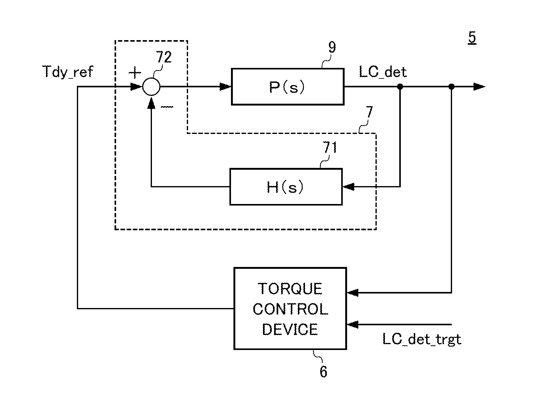
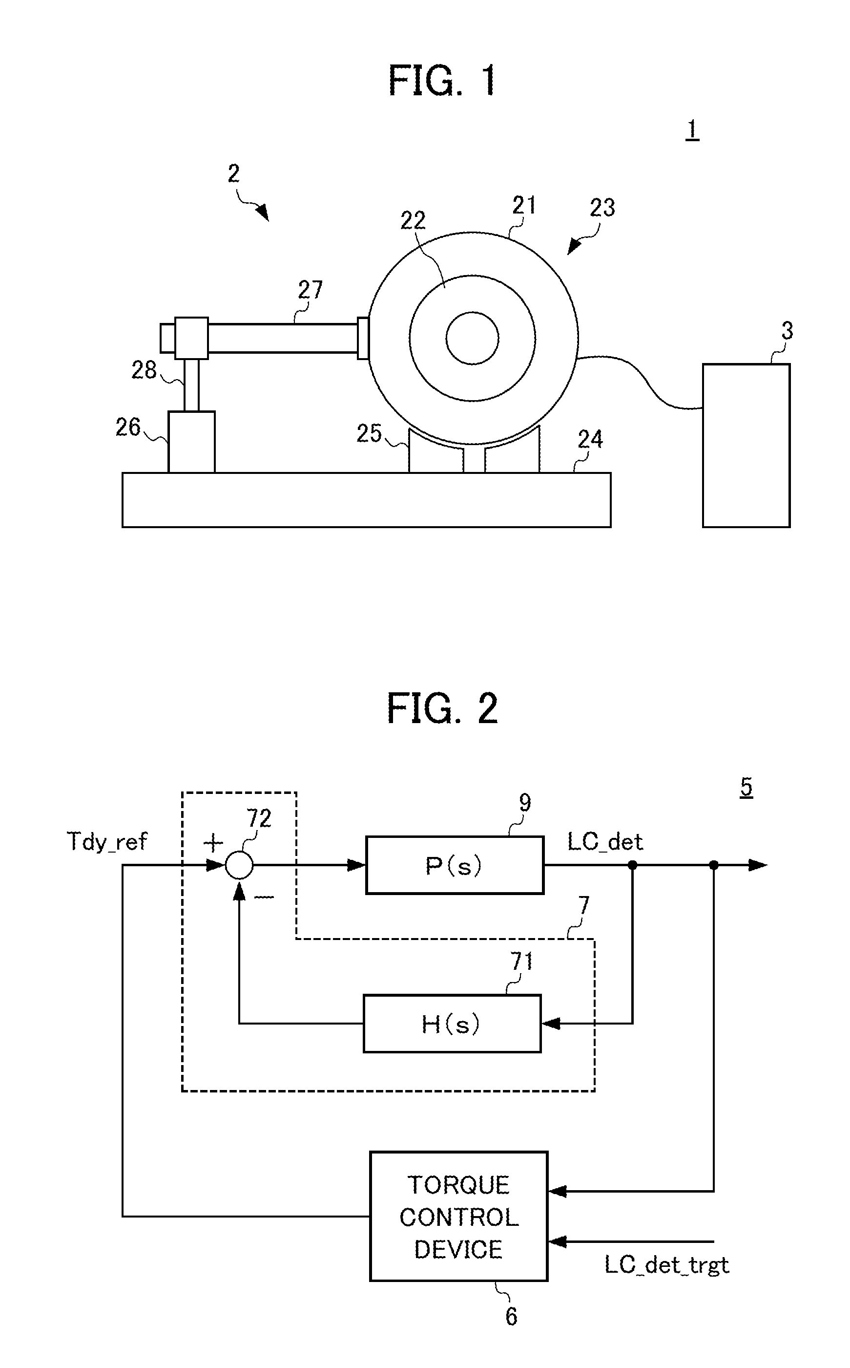
[0051]FIG. 2 is a block diagram showing a configuration of a control device 5 for a dynamometer system of a first embodiment.
[0052]In FIG. 2, a controlled object 9 is configured by including the inverter, the dynamometer, the load cell, etc. described above with reference to FIG. 1. The control device 5 is provided with: a torque control device 6 as a main control device composing a major loop in the control system shown in FIG. 2; and a natural-vibration suppression circuit 7 composing a minor loop in the control system.
[0053]The torque control device 6 outputs a torque current command signal Tdy_ref, based on inputs such as an output signal LC_det from the load cell, and a target value LC_det_trgt thereof. The main control device is not limited to a control device for controlling torque, but may be replaced with a control device for controlling position, speed, running resistance, etc., as long as the torque current command signal Tdy_ref is output as a control input signal.
[0054]...
second embodiment
[0060]FIG. 5 is a block diagram showing a configuration of a control device 5A for a dynamometer of a second embodiment.
[0061]The control device 5A of the present embodiment is further provided with an observer calculation unit 8A, which is a point of difference from the control device 5 of the first embodiment. In the following descriptions of the control device 5A, identical reference numerals are assigned to configurations which are identical to those of the control device 5 of the first embodiment, and descriptions thereof are omitted.
[0062]The observer calculation unit 8A is provided with a vibration output calculation unit 81A, a delay compensator 82A, and a deviation compensator 83A.
[0063]The vibration output calculation unit 81A outputs an approximation signal Pmdl_det, based on an approximation equation shown in the following Equation (7), by using as an input, a sum of the torque current command signal Tdy_ref′ to be input into the inverter, and a feedback signal (to be de...
third embodiment
[0067]FIG. 6 is a block diagram showing a configuration of a control device 5B for a dynamometer system of a third embodiment.
[0068]The control device 5B of the present embodiment differs from the control device 5A of the second embodiment, in terms of a configuration of an observer calculation unit 8B. In the following descriptions of the control device 5B, identical reference numerals are assigned to configurations which are identical to those of the control device 5A of the second embodiment, and descriptions thereof are omitted.
[0069]The delay compensator 82B of the observer calculation unit 8B is configured by connecting a dead-time delay element e−Lmdl·s, which delays the approximation signal Pmdl_det by a predetermined dead time Lmdl, with a lowpass filter element PF—mdl (s) which removes noise from the approximation signal Pmdl_det.
[0070]The controlled object 9B may be provided with a filter PF(s) for removing noise in a high frequency domain. According to the present embodi...
PUM
 Abstract
Description
Claims
Application Information
 - R&D
- Intellectual Property
- Life Sciences
- Materials
- Tech Scout
- Unparalleled Data Quality
- Higher Quality Content
- 60% Fewer Hallucinations
Browse by: Latest US Patents, China's latest patents, Technical Efficacy Thesaurus, Application Domain, Technology Topic, Popular Technical Reports.
© 2025 PatSnap. All rights reserved.Legal|Privacy policy|Modern Slavery Act Transparency Statement|Sitemap|About US| Contact US: help@patsnap.com


