
Nut rotation prevention structure

Active Publication Date: 2014-07-24
HINO MOTORS LTD
View PDF11 Cites 0 Cited by
  • Summary
  • Abstract
  • Description
  • Claims
  • Application Information

AI Technical Summary

Benefits of technology

The patent describes a structure for preventing rotation of a nut on a shaft during tightening. A rotation restriction member is connected to the nut and can be fixed to the shaft in the same position as the nut. The rotation restriction member protects the shaft from external force and distributes the rotational force of the nut across a larger area, making the nut-coupling more stable even during vibration. This eliminates the need to adjust the rotation amount of the nut and ensures a secure and stable attachment of the rotation restriction member to the shaft.

Problems solved by technology

Thus, adjustment of the rotation amount of the nut 15 may drastically deteriorate the bearing performance.
This problem is not limited to the front axle and also applies to the rear axle.

Method used


Image

  • Nut rotation prevention structure
  • Nut rotation prevention structure
  • Nut rotation prevention structure

Examples


first embodiment

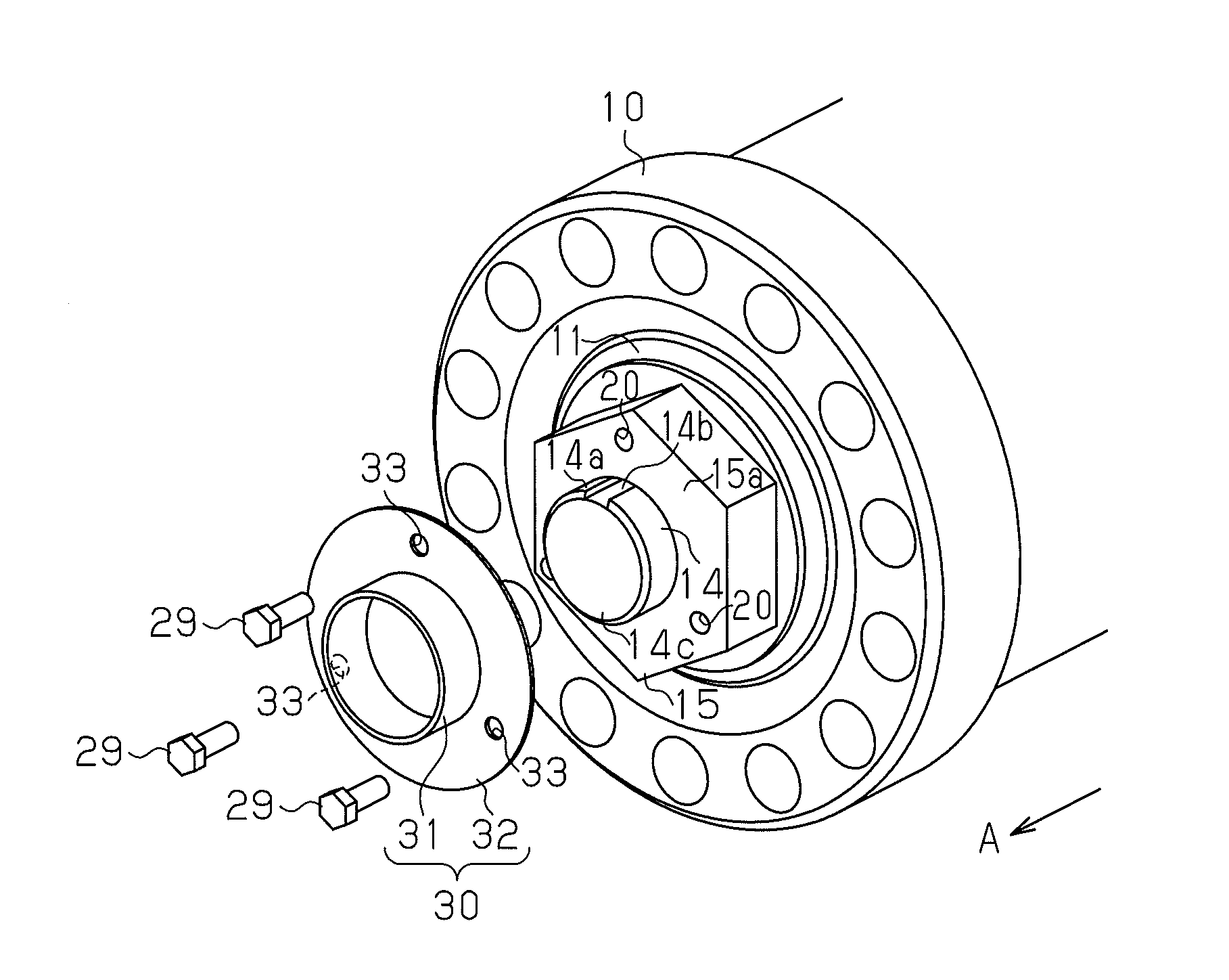
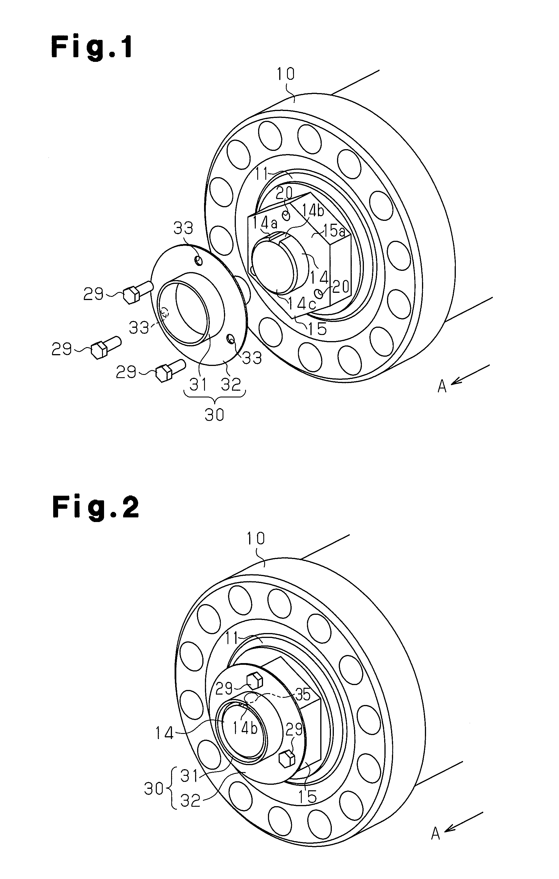
[0028]A first embodiment of a nut rotation restriction structure according to the present invention will now be described with reference to FIGS. 1 and 2. In the first embodiment, members that are the same as those shown in FIGS. 5 and 6 are denoted by the same reference characters and will not be described in detail.

[0029]As shown in FIG. 1, in the first embodiment, a knuckle spindle 14, which serves as a shaft member rotatably supporting the wheel hub 10, includes a projection 14a, which serves as a first portion projecting from the wheel hub 10. Male threads (not shown) are formed on an outer surface of the projection 14a. The knuckle spindle 14 includes a key groove 14b that has an opening in a distal end surface 14c and extends in the axial direction A.

[0030]A nut 15, which is fastened to the male threads of the knuckle spindle 14, is a so-called hexagonal nut and includes three female threaded portions 20 that are arranged in an end surface 15a in the circumferential direction...

second embodiment

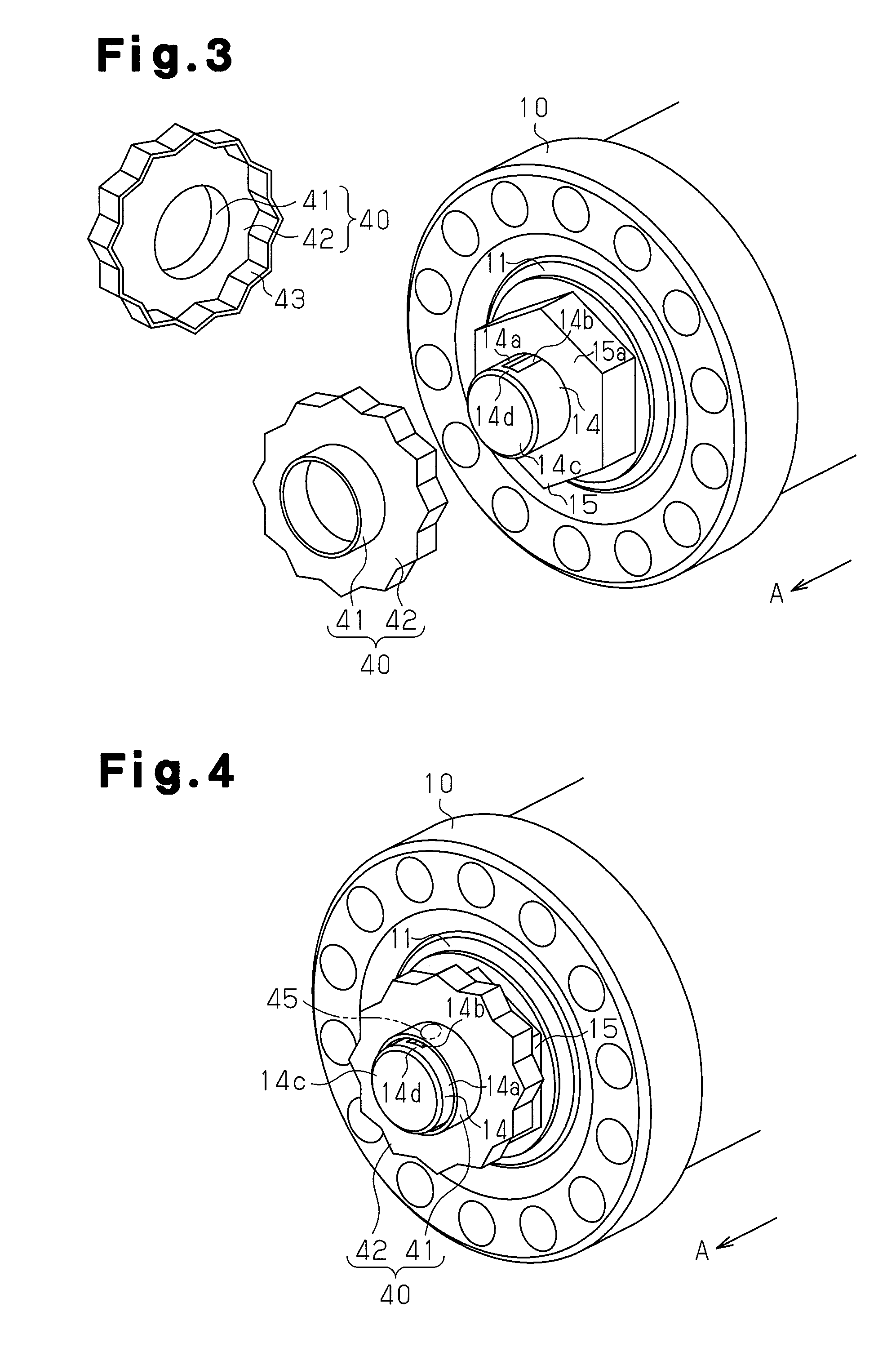
[0047]A second embodiment of a nut rotation restriction structure according to the present embodiment will now be described with reference to FIGS. 3 and 4. In the second embodiment, members that are the same as those shown in FIGS. 5 and 6 are denoted by the same reference characters and will not be described in detail. Further, in the second embodiment, the method for coupling the rotation restriction member to the nut differs from the first embodiment. The different parts will be described in detail.

[0048]As shown in FIG. 3, in the second embodiment, the knuckle spindle 14 includes a closed portion 14d forming one end of the key groove 14b and located toward the basal end from the distal end surface 14c. The nut 15, which is a hexagonal nut, includes a flat end surface 15a, which serves as a contact surface.

[0049]A rotation restriction member 40 includes a sleeve 41, into which the knuckle spindle 14 is inserted, and a coupling portion 42, which is formed integrally with the basa...


PUM


Abstract

A nut rotation prevention structure is provided with a shaft member, a nut, and a rotation prevention member. A wheel hub is supported by the shaft member. The nut is engaged through threads with a first portion of the shaft member, the first portion protruding from the wheel hub. The rotation prevention member is mounted to a second portion of the shaft member and prevents the rotation of the nut, the second portion protruding from the nut. A key groove is formed in the second portion. The rotation prevention member has a tube-shaped section and a connection section. A portion of the shaft member, the portion having the key groove formed therein, is inserted in the tube-shaped section. The connection section connects the tube-shaped member to the nut. The tube-shaped section is affixed to the key groove by staking.

Description

TECHNICAL FIELD[0001]The present invention relates to a nut rotation restriction structure applied to, for example, a nut used to couple a wheel hub to a shaft member, such as a knuckle spindle or an axle housing.BACKGROUND ART[0002]In the prior art, a wheel hub is coupled to a knuckle spindle by a nut and supported to be rotatable by the knuckle spindle in a front axle portion of a vehicle. FIG. 5 is a cross-sectional view showing a coupling structure in which a wheel hub is coupled to a knuckle spindle by a nut.[0003]Bearings 11 and 12, which are arranged in a wheel hub 10, support the wheel hub 10 to be rotatable on a knuckle spindle 14 of a knuckle 13. The knuckle spindle 14 includes a projection 14a that projects from the wheel hub 10. Male threads (not shown) are formed on an outer surface of the projection 14a. A nut 15 is fastened to the projection 14a with a predetermined tightening torque so that a proper pre-load is applied to the bearings 11 and 12.[0004]A wheel 16 and a...

Claims


Application Information

Patent Timeline
IPC IPC(8): F16B39/12
CPCF16B39/12F16B39/103F16C25/06F16C19/548F16C2226/60
Inventor MIZUNO, SHIGETO
Owner HINO MOTORS LTD
Learn More